In this experiment we will use various instruments to study the behavior of inductors in DC and AC circuits.
Equipment List: Test Equipment.
ÃÂ DMM: Fluke model 77, serial 9801 ÃÂ Tectonics Oscilloscope: Model 2213A, serial P1097 ÃÂ Function Generator: Model 3311A, serial 925577 ÃÂ Decade Inductor: Model ALD-12, serial 3735 ÃÂ Harrison DC Power Supply: Model 6200B, serial T5599 Equipment: ÃÂ One 2.2k ohm resistor ÃÂ One 200 ohm resistor ÃÂ One 1N4002 diode Theory: An ideal inductor offers no resistance to the flow of direct current. However, all inductors do have some internal DC resistance, which is easily measured, and may be used to be represented as a separate element in series with the inductance. With regard to AC inductors do impede the flow of AC current.
Procedure 1 (Inductor in Circuit with DC Source) 1. Assemble the circuit as shown below. (The power supply is a DC sourse).
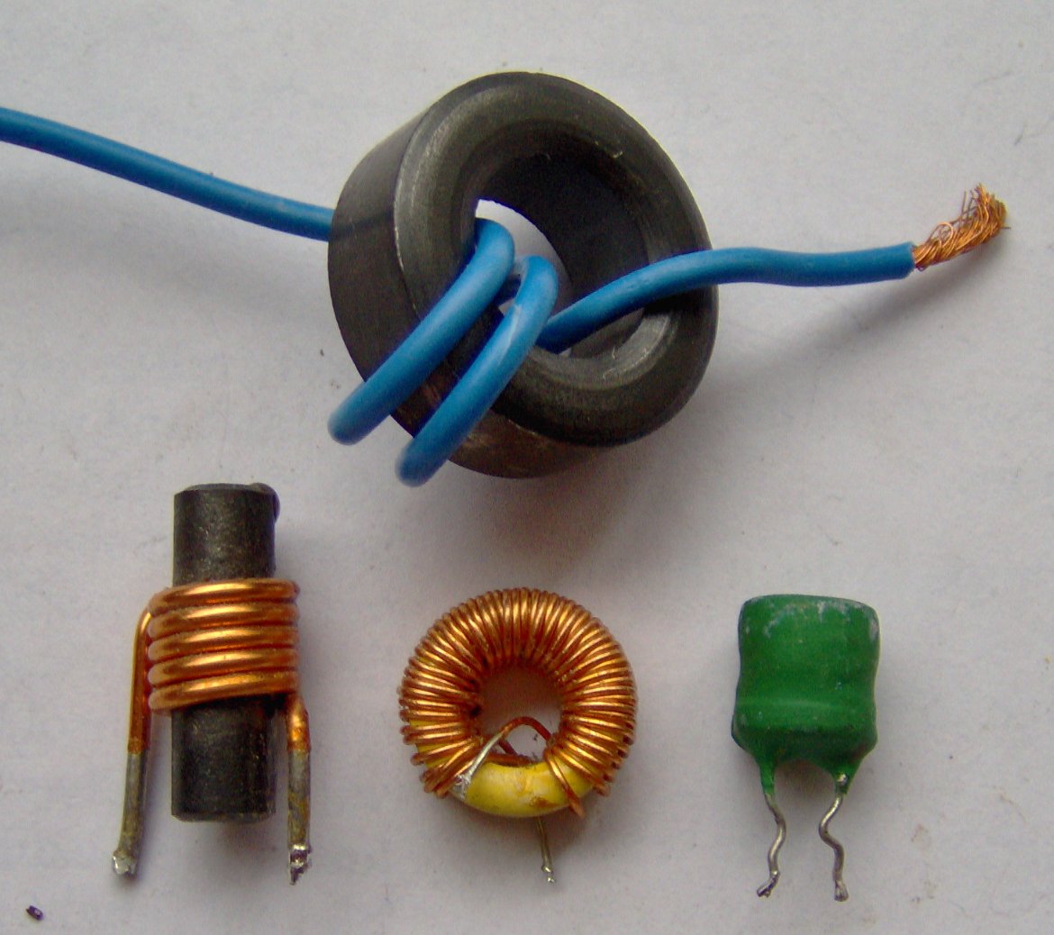 Electronic component - various small inductors
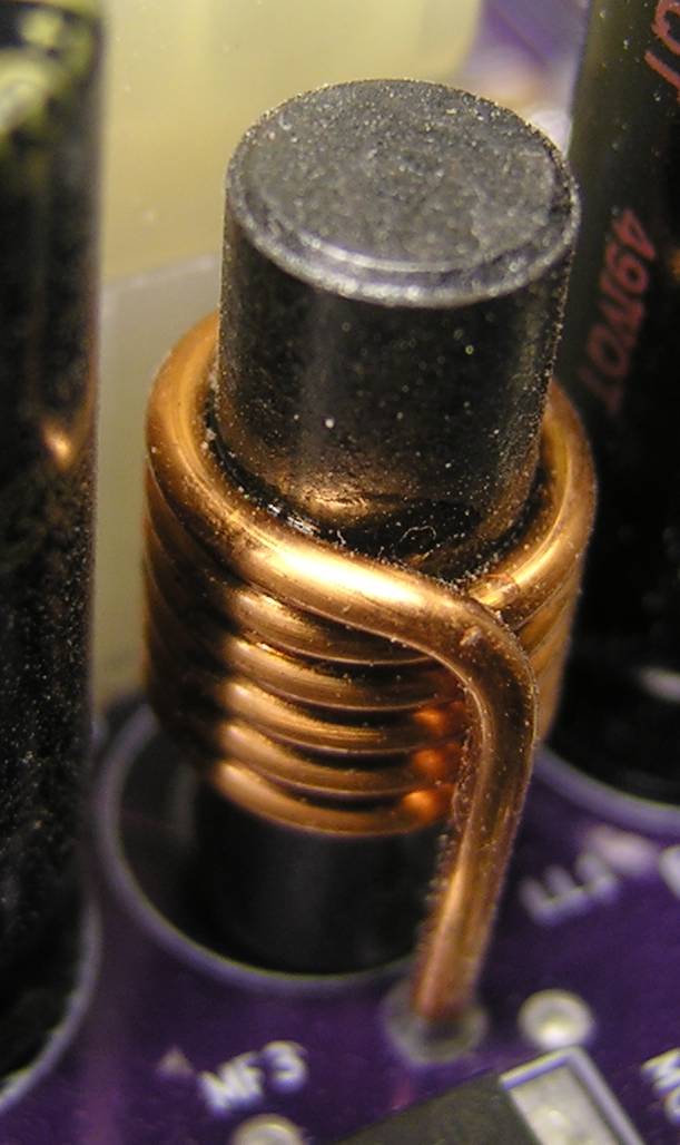 An inductor.
 JetNetherlands Dassault Falcon 2000EX PH-VBG
2. Set the DMM to measure voltage in DC. Observe and record the DC voltages across Vag, Vab and Vbg with the DMM.
a. Vag should be around 7.67V b. Vab should be around .397V c. Vbg should be around 7.28V 3. Set the DMM to measure current. Connect the DMM to measure the current in the circuit by breaking the circuit.
a. Current should be around 3.34Amps 4. Remove the inductor from the circuit and measure its DC resistance with the DMM.
a. The resistance should be around 118.5 ohms Procedure 2 (The Inductor as a Filter Element) 1. Assemble the circuit as show in the figure below. (The power supply is an AC source).
2. Adjust the function generator to yield zero DC output, and a 5Khz sinusoidal with peak-to-peak amplitude of 10 volts.
3. Observe and record the voltages across Vag and Vbg, with the inductance set to 1H. Use the oscilloscope as well as with the DMM voltmeter over the same points.
a. Vag should be around 9.6V peak-to-peak b. Vbg should be around .56V peak-to-peak 4. Repeat step 3 with the inductance set to 0.5H.
a. Vag should be around 9.6V peak-to-peak b. Vbg should be around 1.1V peak-to-peak 5. Repeat step 3 with the inductance set to 0.2H.
a. Vag should be around 8.8V peak-to-peak b. Vbg should be around 2.7V peak-to-peak Procedure 3 (The inductor as a Series Filter Element with DC & AC Source Present) 1. Assemble the circuit as show in the figure below. (The power supply is an AC source in series with a DC source).
2. Adjust the function generator to yield zero DC output, and a 5Khz sinusoidal with peak-to-peak amplitude of 5 volts.
3. Set the DMM to measure voltage in DC. Observe and record the DC voltages across Vag and Vbg with the DMM.
a. Vag should be around .216V b. Vbg should be around 4.97V 4. Observe and record the voltages across Vag and Vbg, with the inductance set to 1H. Use the oscilloscope as well as with the DMM voltmeter over the same points. (Make sure that the scope is set for Direct Coupling "DC" not AC).
a. Vag should be around 4.8V peak-to-peak i. With a maximum peak voltage of 7.2V b. Vbg should be around .56V peak-to-peak With a maximum peak voltage of 7.6 Procedure 4 (The Inductor as a Shunt Filter Element With DC & AC Source Present) 2. Assemble the circuit as show in the figure below. (The power supply is an AC source).
3. Adjust the function generator to yield zero DC output, and a 5Khz sinusoidal with peak-to-peak amplitude of 5 volts.
4. Set the DMM to measure voltage in DC. Observe and record the DC voltages across Vag and Vbg with the DMM.
a. Vag should be around 5.01V b. Vbg should be around .044V 5. Observe and record the voltages across Vag and Vbg, with the inductance set to 1H. Use the oscilloscope as well as with the DMM voltmeter over the same points. (Make sure that the scope is set for Direct Coupling "DC" not AC).
a. Vag should be around 4.8V peak-to-peak i. With a maximum peak voltage of 7.6 b. Vbg should be around 4.4V peak-to-peak Procedure 5 (Inductive Kick) Theory of Inductive Kick: One property of an inductor is that the current flowing through it cannot change abruptly. This can lead to the phenomenon know as "inductive kick," upon the opening of an inductive circuit. This can manifest itself by high spike of voltage (glitch) or an arc at the switch contacts.
1. Assemble the circuit as show in the figure below. (The power supply is a DC source).
2. Alternately close and open the switch (use a jumper). Observe the brief flash of the LED when the circuit is opened.
a. You should see the LED flashing on and off.
Analysis: 1. In the first procedure, in which an inductor was used in series with a DC source it had a noticeable effect on the circuit. The current in the circuit was 3.34Amps; the inductor caused the voltage across point Vag to drop from 10 volts to 7.67volts due to its high resistance.
2. In the second procedure in which the inductor was used in series with an AC source and a resistor there also was a noticeable effect on the circuit. When the inductor was in series total voltage 9.6V peak to peak, when the total voltage started at 10V peak to peak across point A in respect to ground (point G).
3. The inductor effects the voltage in the circuit in which both a DC and AC sources were present. The DC value of the voltage in the circuit at point Vbg went up to 4.97V. The inductor caused the AC sin wave to shift up on the oscilloscope. Which took increases the peak voltages for point Vbg (5.7v Peak).
4. The inductor also affects the voltage when the resistor is placed before the inductor. The DC voltage across Vbg decreased drastically to 0.044V because of the change in the circuit. The AC voltage also decreased like the DC voltage. The AC voltage peak-to-peak went to 4.4Vpp for point Vbg.
5. The inductor in the inductive kick procedure affected the way the LED preformed. The LED does not emit light when the switch is closed because there is not enough voltage going through the circuit to keep the LED lit. The current in an inductor cannot change abruptly, which can be a cause for an "inductive kick." An inductive kick is a high spike of voltage at the switch contacts. The voltage can change instantly but he current can't so as soon as the voltage source is disconnected the voltage instantly changes causing the LED to light up but since there is not enough change in current to keep the voltage up the LED only flashes briefly.
 Untitled Dassault Falcon 2000EX; PH-VBG@ZRH;28.04....
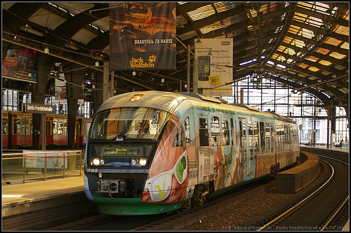 VT 06 / 642 306-4 D-VBG