SUMMARY
The Lathe is the father of all machines tools and is recorded in the early history of many races. As interchangeable manufacturing and mass-production principles were developed, it became necessary to create machine tools capable of producing parts in large quantities.
This report aims to consider five different "Types of Lathe" in relation to their manufacturing application, as well as, comparative of important aspects for manufacturing and mass production. It will concentrate on the traditional centre lathe and its development into: production lathes.
Definitions, graphs and figures are also included in this report.
ç CONTENTS
1. INTRODUCTION 4
1.1.PROCEDURES 4
1.2.TOPICS COVERED 4
1.3.TERMS OF REFERENCE 4
2. THEORETICAL BACKGROUND 5
3. TYPES OF LATHES, COMPONENTS AND OPERATORS 5
3.1.CENTRE LATHE 5
3.2.PRODUCTION LATHES 6
3.2.1. Capstan and Turret Lathes 6
3.2.1.1. Capstan Lathe 6
3.2.1.2. Turret Lathe 7
3.2.2. CNC Lathe. 7
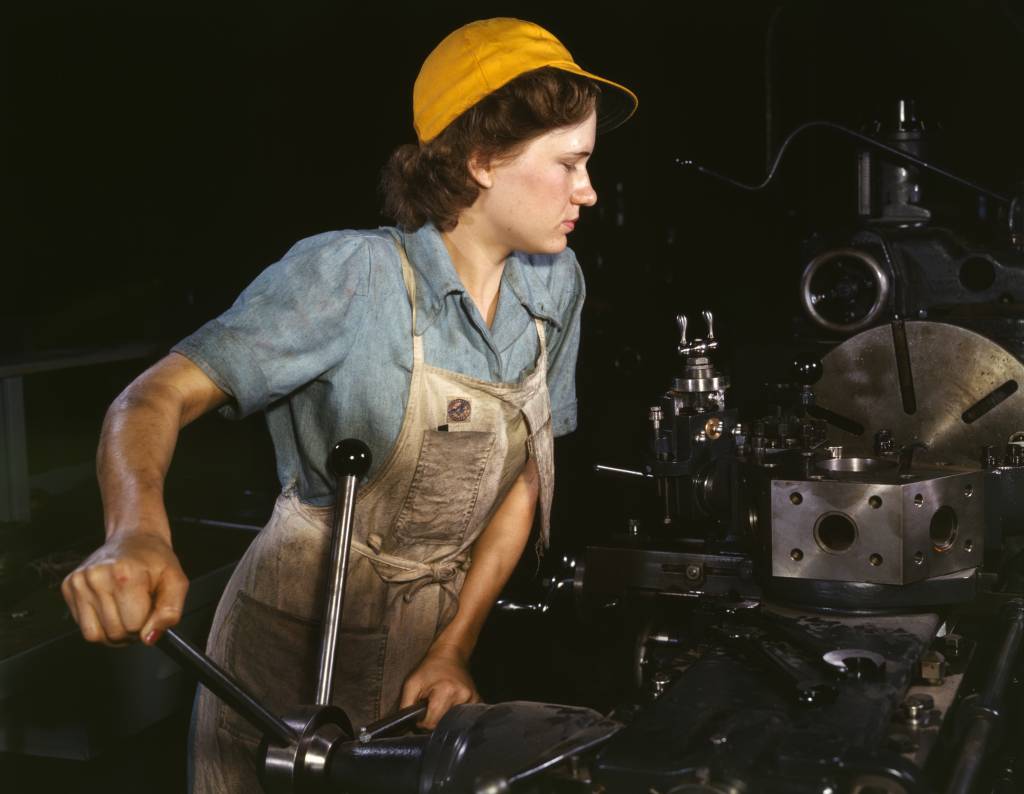 Lathe operator machining parts for transport plane...
 Conventional lathe. Author : Greudin, 2003. Licenc...
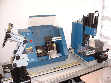 English: Training FMS with learning robot, workben...
3.2.3. Single-Spindle Automatic Lathe. 8
4. WORK HOLDING AND TOOL HOLDING SYSTEM 9
5. SETTING UP AND PROGRAMMING 11
6. THE MEASURING GAUGING SYSTEM 12
7. ECONOMIC ASPECTS 13
8. REFERENCES 15
1. INTRODUCTION
1.1. -TERMS OF REFERENCE
1.1.1. - According to the instructions given by Michael Thomas (Module Leader), for "Manufacturing and Basic Materials" at University of Glamorgan School of Technology, this report has been required and set up as a part of the final assessment.
1.1.2. - The proposal of this report considering five different "Types of Lathe" in relation to their manufacturing application.
1.1.3. - This report has been assessed and written by Victor Martinez-Perez "First Year Student of BEng (Hons) Mechanical Engineering at the University of Glamorgan-Pontypridd, Wales
1.2. -PROCEDURES
Research for this report was conducted in two ways:
1.2.1. Research from lecture notes and reference books.
1.2.2. Research on the Internet.
1.3. - TOPICS COVERED
This report it will concentrate on the traditional centre lathe and its development into: production lathes, in relation to their manufacturing application.
2. THEORETICAL BACKGROUND
Man has always tried to find ways of making manual tasks easier and businessman methods to reduce manpower, speed production and lower operating costs.
The Lathe is the father of all machines tools and is recorded in the early history of many races, when, equipped with a fixed tool-rest, it was used for woodturning. For its development to the form in which it is known it today, Henry Maudsley (1797) developed the slide rest lathe, allowing people to turn large pieces of metal very quickly and with exact precision. To many people it was regarded as the most important development in the production of machine tools [1]. As interchangeable manufacturing and mass-production principles were developed, it became necessary to create machine tools capable of producing parts in large quantities.
Today an Engine Lathe can be defined as a power-driven, general-purpose machine tool used for producing cylindrical work-pieces. As the piece of metal to machine is rotated in the lathe, a single point cutting tool is advanced radially into the workpiece at a specified depth and moved longitudinally along the axis of the workpiece removing metal in the form of chips. By using attachments and accessories other operations may be performed [4]. Lathes are used to produce circular, conical, flat or sphericall components. [13]
Common external lathe processes: facing, straight turning, taper turning, threading.
Common internal lathe processes: drilling, boring, internal straight and taper turning, countersinking, counter boring, reaming, tapping and threading
The progress in the design of the basic engine lathe and its related machines has been responsible for the development and production of thousands of products we use every day.
3. TYPES OF LATHES, COMPONENTS AND OPERATORS
3.1. CENTRE LATHE
The engine lathe is generally used for machining individual parts to the required specifications. Some of the common operations performed on a lathe are: facing, taper turning, parallel turning, thread cutting, knurling, boring, drilling, and reaming. [4]
An engine lathe is shown diagrammatically in (Figure-1): it consists of a horizontal bed supporting the headstock, the tailstock and the carriage. All machine tools must have a means of supporting or holding the workpiece. The tailstock can be clamped at various positions along the bed to accommodate workpieces of various lengths. Short workpieces need only be gripped by the chuck.
Figure-1
The basic lathe requires a skilled operator and the quality of work produced will depend on his/her care and attention. For production work it is desirable to eliminate the possibility of variation and error, and to this end mechanical stops are often fitted to the carriage to allow accurate return to position and also to disengage power feeds when the required cut is completed. [4]
The capstan lathes are ideal for manufacture of simple and complex turned parts, both from bar and blanks. The blanks can be preturned, forged or cast.
3.2. PRODUCTION LATHES
Production Lathes are generally used when a large number of duplicate parts must be produced. Capstan and Turret Lathes, Single-Spindle Automatic Lathes, and the CNC Lathe are the common machines in this group.
3.2.1.Capstan and Turret Lathes
Capstan and Turret Lathes are essentially similar in their general arrangement and operation. They differ in many ways from the centre lathes. They are more rigidly constructed, more powerful and have shorter and more rigid beds. There is no compound slide and the tool post is usually a four-way turret mounted directly on the front of the cross slide. The rear of the cross-slide also carries a simple tool post for the parting off tool when working from the bar. An indexing turret replaces the tailstock and it is this turret that carries the majority of the tooling. The tooling is pre-set and the turret can be indexed, or rotated to bring each tool into position, as it is required.
3.2.1.1. The Capstan Lathe is the smaller and most frequently used for bar work fitted with a collet chuck. Its turret is carried on a separate sub-bed that can be clamped at any point along the main bed. The clamping is more rigid and permanent as the sub-bed is only set infrequently. The turret turns automatically from station to station. The turret slide is fitted with adjustable stops, which limit its motion towards the headstock. The operator does not have to carry out any measuring processes but merely feeds the tool into the work until the stop prevents further movement. The tool is then withdrawn manually and the net tool is used. The stop is automatically changed as each new tool is indexed into position.
3.2.1.2. The Turret Lathe is larger and heavier and is used for machining large castings. It is the next development in the provision of a production machine for use by an unskilled operator. The turret lathe is usually fitted with pneumatically or manually operated chucks or special turning fixture to hold the workpiece. The main difference with the capstan lathe is that the turret is mounted on a carriage that slides directly on the main bed of the machine. Indexing is not automatic but is performed manually after unlocking the turret. In this the cross slide is simplified, and provided with a single inverted tool post at the rear and a square indexing turret carrying up to four tools is fitted at the front. A numbered drum of stops is provided for longitudinal and transverse motions. All that is required of the operator is that he/she indexes turret and drum, and moves the carriage to the preset stop. On some turret lathes, as many as 20 different tools can be mounted on a ram or saddle-type turret, and each tool may be rotated into position quickly and accurately. Once the tools have been set, each part is quickly and accurately produced. [8]
3.2.2. CNC Lathe.
A computer numerical control (CNC) (figure 2) machine is one of the latest modifications of the basic engine lathe and it is a NC machine with the added feature of an on board computer.
Figure 2.- CNC Lathe
This lathe controlled by numerical tape is used primarily for tuning operations and can economically and automatically produce shafts of almost any shape. This lathe can outperform most types of lathes and provides savings in tooling, set-up and cycle time.
By the term numerical control, we mean that a machine tool can be operated automatically by means of a medium (a paper tape). The tool will do only what it is told to do by the tape that is fed into the machine. But the term computer numerical control (CNC) refers to a computer that is joined to an N/C machine. This makes the machine more versatile because now we can store information in a memory bank, with retains what is on the N/C tape and repeats it without the tape having to be rewound each time. You can also program a job manually, stop by step, directly on the machine; this is called manual data input. In both cases you can now make a new tape or change what is in the memory bank by making a new tape. This costs more, but the operator now has greater flexibility in producing the part. For example if a tool gets dull you can manually change the feed of the speed of the cutter to maintain a smooth cut. The cutter can therefore cut up to 10 more parts before an operator has to change the tool. This increases the number of parts per tool and reduces the downtime of a machine, which is very profitable. If a company needs to add or delete sections of a part for revisions or updating can do it by pressing two to four buttons.
In a CNC lathe the drives of the hand wheels of the conventional lathe have been substituted to allow their control of slide positions by the computer. This opens up the possibility of generating unlimited variety of profiles using continuous positions control of the slides. [3]
This can then be extended by the installation of tool turrets under computer control, and a computer controlled turret on longitudinal and transverse slide ways replacing the tailstock. Since provision has no longer to be made for a human operator, the machine can be made more compact and complex. The bed can be redesigned and placed at a slope to allow improved flow of coolant. Driven spindles may be incorporated into the tool turrets, enabling milling and drilling operations to be carried out, and allowing complex parts to be produced complete in one operation.
3.2.3. Single-Spindle Automatic Lathe.
This lathe differs from the capstan in that the turret revolves about a horizontal pivot instead of about a vertical axis. It will also possess several radial tool slides used for forming and parting tools.
This lathe is particularly popular as a first operation machine fed with bar stock, using a magazine type bar feeder. Produce in small (figures 6 and 7) and medium quantities. It is designed to turn small parts normally used in cameras, electronic gadgets, spray guns, hydraulic & pneumatic and fittings, cable glands, etc, made out of aluminium, brass or mild steel. These can also produce automobile-related parts, like pistons, rings, valve guides, shafts, ejector pins, etc. Some work examples are shown below.
The control of the machining cycle no longer rests with the operator, but is controlled by the machine itself usually by cam-actuated motions.
4. WORK HOLDING AND TOOL SYSTEMS
4.1. WORK HOLDING
The chuck is the most common method of work holding. (Figure-8). The chuck has either three or four jaws and is mounted on the end of the main spindle. A three-jaw chuck is used for gripping cylindrical workpieces when the operation to be performed is such, that the machined surface is concentric with the work surfaces. The jaws have a series of teeth that mesh with spiral grooves on a circular plate within the chuck. This plate can be rotated by the key inserted in the square socket, resulting in simultaneous radial motion of the jaws. Since the jaws maintain an equal distance from the chuck axis, cylindrical workpieces are automatically centred when gripped.
With the four-jaw chuck, each jaw can be adjusted independently by rotating the radially mounted threads screws. Although accurate mounting of a workpiece can be quite time consuming, a four-jaw chuck is often necessary for non-cylindrical workpieces.
For very complicated shapes a circular faceplate can be used. The faceplate has radial slots that provide a means of bolting the workpiece to the faceplate.
For small lathes for work on material provided in bar form, collets are often used. These collets are effectively split sleeves that fit snugly over the workpiece and have a taper on their outer surface. Drawing the collet into a matching tapered hole in the end of the spindle has the effect of squeezing the collet and gripping the workpiece.
For accurate turning operation or in cases where the work surface is not exactly cylindrical, the workpiece can be turned between centres. (Figure-9). Initially the workpiece has a conical centre hole drilled at each en to provide location for the lathe centres. Before supporting the workpiece between the centres (one in the headstock and one in the tailstock), a dog (a clamping device) is secured at the headstock end. The dog is arranged so that the tip is inserted in a slot in the drive plate mounted on the main spindle, ensuring that the workpiece will rotate with the spindle. [11]
In the collet chuck, there is a spring collet split at its front end. The work is first clamped by making the collet close upon the workpiece by means of a nut.
Face plates are used for irregular shapes. A faceplate has radially place slots, which allow the workpiece to be clamped to it by means of bolts
Although similar forms of work holding are used as for traditional machines they are automated and may have locating systems incorporated into them. Automation of chuck closure can be achieved by mechanical, pneumatic or hydraulic actuation.
4.2. TOOL HOLDING
It is often the case that the most difficult stage in manufacturing a product is working out how to hold a billet of material while it is machined. The tool must not foul the working holding system. The work holding system must not get in the way of the machining operations. [6]
Lathe cutting tools are generally held by two methods:
÷ In tool holders, which provide rigidity when holding the cutting tool.
÷ In tool posts: which provide a means of holding either a toolholder or a cutting tool
Standard
The toolpost usually supplied with a centre lathe is the standard or round type (Figure-10). This toolpost, which fits into the T-slot of the compounds rest, provides a means of holding and adjusting a toolholder or a cutting tool. A concave ring and wedge provide a means of adjusting the cutting tool height.
Turret type or four-way toolpost
Turret type or four way tool post (Figure-11) are designed to hold four cutting tools, which can be easily indexed for use as requires, Several operations, such as tuning, grooving, threading, and parting may be performed on a workpiece by loosening the locking handle and rotating the holder until the desired tool bit is in the cutting position. This reduces the set-up time for various too/bits, and thus increasing production.
Quick-change tool holder
These are made in different styles to accommodate different types of cutting tools. Each holder is dovetailed (Figure-12) and fits on a dovetailed toolpost, which is mounted on the compound rest.
The tool is held in position by a set of screws. After a tool becomes dull, the holder and the tool may be replaced with another preset unit. This is useful where many parts of one size are being machined since the cutting point on the toolbit, having been preset in the tool room, is in exactly the same position as the tool it replaces. Each toolholder fits onto the dovetail on the toolpost and is locked in position by means of a clamp. A knurled nut on each holder provides vertical adjustment.
The main difference between traditional tool holding and CNC tool holding is the use of presetting. This can be achieved in a number of ways such as tooling held in locatable tool holder, Block tooling and changeable tool/tip elements.
Tool presetting systems use special presetting fixtures of possible co-ordinate measuring systems. Once the tool has been mounted into the turret proving systems can be used to account for small inaccuracies in setting in addition to tool wear.
5. THE SETTING UP AND/OR PROGRAMMING OF THE LATHE
The best lathe in the world is going to function poorly unless it's correctly set up in the first instance. Even a new lathe will not cut parallel unless it's levelled properly, and the surface finish that can be achieved will be much improved by reducing vibrations transmitted to the work and tool from the motor and lathe gearing. As well if the lathe has been installed for some considerable time it's worth going through the test procedures to check its alignment. None of the procedures involved are particularly complex, and it doesn't require expensive tools to get a good end result
The process of setting the lathe up is a logical one, and the first step is to check that the foundation is as level as you can possibly get it.
Secondly correct twist in the bed is a simple matter of adjusting the jacking screws on the raising blocks, or by placing shims beneath the feet of the lathe - such adjustments being carried out at the tailstock end.
Setting Up cutting tool
The cutting tool must be set up at he correct height. If it is set too high then the tool will rub against the workpiece, generating heat and a poor surface finish and blunting the cutting tool edge. If the cutting tool is set too low then the workpiece will be pulled over the top of the cutting tool and will damage the cutting tool or pull the workpiece from the chunk. The severity of the problem will be determined by the forces involved, which are related to the height above or below the workpiece centre and the materials, feed rate, cutting speed and depth of cut that are involved. The cutting tool must also be held tightly in the tool-post, using all available clamping screws. The cutting tool should not extend further than is necessary from the tool-post, as this increases the risk of vibration, resulting in damage to the cuttings tool and poor surface finish and tolerance.
CAD/CAM links
The wide use of CAD systems has led to major developments in the generation of CNC programs. The computer "knows" de geometry that the designer has defined. It stores the values of the equations of the lines and circles, etc in its memory. This means that the geometry can be transferred to the CAM program which adjusts the sizes produced by the designer to produce a new set of geometry to define the cuter path needed to make the part. Someone thus has to define which cutter; feed rate and spindle speed will be used. These are technology decisions usually made by the manufacturing engineer how has to take into consideration the strength of the workpiece material, the clamping and the amount of material to be removed.
It is now a usual practice to download the geometry specified by the designer and then to process this into a machining program. This can save considerable amount of time and also prevents errors that the programmer can make when doing calculations and retype the dimensions into the computer. It does also place the responsibility for the product shape upon the designer. The drawing must be free of errors, as it will be followed faithfully by the CAM system.
Unfortunately the machine tool builders have not agreed a universal standard for the machine language. This forces companies to use post processors to translate from the ISO CL file CAM output, into the particular machine tool language. Similarly CAD systems have their own individual formats and the International Graphic Exchange Standard has been established to enable companies to exchange CAD information across different systems. A widespread of this is used by Auto CAD, DXF format and most CAM systems will accept a DXF or IGES files as an input. [10]
Editing facilities enhances the utilisation of the machine considerable as programmes may be copied to enable several parts to be made from one piece of material and kits of parts may be made at one setting on the machine.
6. THE MEASURING GAUGING SYSTEM
Thanks to the advances in technology, machines have been developed which are capable of producing workpieces to extremely fine tolerances. As a result, measuring tools and equipment had to be upgraded to measure the closer tolerances accurately. The need for accurate measurement was necessary because of interchangeable manufacture, where parts produced in one part may be assembled with parts from another plant or even another country. [12]
Using a centre a thorough the inspection is a must although accuracy of the workpiece required would determine the type of measuring tools which should be used. [4]
A hook rule is very convenient for measuring the size of a workpiece.
Inside callipers will be used to measure the diameter of holes or the width of key ways and slots and then will be transferred to a micrometer.
A micrometer may be used to measure the shaft of the work in a machine.
Vernier callipers are used to measure with precision.
Plug gauges are also used to measured holes.
Dial indicators are used to check the alignment of machine tools, fixtures and work pieces prior to machining
7. ECONOMIC ASPECTS
In any engineering operation, the economics of cost of operation plays a vital role in determining the rate or speed of operation. If we cut the unwanted material at a very slow speed, the completion time of the operation would increase. And with it the cost of labour, the cost of machine operation, and the overhead costs and make the operation costlier. If the same operation were done at very high speed, the wear of cutting tool would be accelerated. The operator will have to change the tool more often and, consequently will have to regrind the tool and reset it on the machine more frequently. Thus will increase the tool cost, the tool resetting cost and machine down-time. The effect of speed on various costs is illustrated in (Figure-13), which shows that only at some particular speed the operation is most economical. [9]
The approach to automation depends heavily on the volume of production. Usually three categories are used in describing the volume of production: mass production involving more than 1 million components per year, large-batch production and small batch-production less than a few hundred in each production run.
A numerically controlled machine where the operator is replaced by feedback control equipment, containing the various instructions are generally economical for the machining of those medium components that are required in small batches and that do not need a wide variety of machining operations using different tool systems and different positions of the workpiece.
Complex components are expensive because they have considerable material value and generally require a large amount of machining. For this components the most economical is to choose a machine where in a variety of machining functions are integrated. For instance the ASS.
Mr. After Debarr [12] compared manufacturing costs for various systems quantitatively. This comparison is presented in (Figure-14) and shows how the choice of systems depends to a large extent on batch size. It is clear that manual systems are only justified for the smallest batches and that numerical control is likely to be economic for a wide range of small and medium batch production.
Accuracy and surface finish must to be taken into consideration as well when costs are concerned and is therefore necessary to take into account the function intended for the machined surface. The specification of too-close tolerances or too-smooth surfaces is of the major ways a designer can add unnecessary costs. As a guide to de difficulty of machining to within required tolerances it can be stated as:
÷ Tolerances from 0.127 to 0.25 mm are readily obtained.
÷ Tolerances from 0.025 to 0.05 mm are slightly more difficult to obtain and will increase production costs.
÷ Tolerances 0.0127 mm or greater require good equipment and skilled operators and will add significantly to production costs.
Even when the surface can be finished on the one machine, a smoother surface requirement will mean increased costs.
The typical surface roughness obtained in turning is between 6.3 to 2.5 ìm.
The machining time and hence the machining cost is inversely proportional to the square root of the surface finish. (Figure-15), shows the relationship between production cost and surface finish for a typical turning operation.
8. REFERENCES
[1]Titlt Hammer - Steel City Founders http://tilthammer.com/bio/maud.htm
[2] http://www.the-land-rover.com/WeldShop/MasterMachinist/Ch7.htm
[3] J. V. Valentino and Joseph Goldenberg. Introduction to Computer Numerical Control (CNC). Third Edition. Pearson Education.
[4] James Anderson and Earl E. Tatro. Shop Theory. Sixth edition. McGraw-Hill 1974
[5] http://www.welsoft.co.uk/machmill/hs410.htm
[6] H Burghardt, A Axelrod & J Anderson, Machine Tool Operation, Part 1, ED McGraw Hill Book Company, 5th Edition
[7] G. Sekhon & B Juneja, Fundamentals Of Metal Cutting and Machine Tools, Ed John Wiley & Sons, Chichester 1987
[8] Krar, Oswald & St. Amand Machine Tool Operations, McGraw Hill, Inc. 1985
[9] A J Lissaman & S J Martin Principles of Engineering Manufacture, Ed Arnold, London 1996
[10] R Rapello, Essentials of Numerical Control, Ed Prentice Hall, New Jersey 1986
[11] G Boothroyd, Fundamentals of Metal Machining and Machine Tools, International Edition Ed. McGraw Hill Company, Singapore 1987
[12] R L Timings, Manufacturing Technology, Level 2, 2nd Edition. Ed Logman Technician Series, London 1984