The difference between PLCs and other computers is that PLCs are made to work in dust, moisture, heat, cold and have room for many inputs, outputs. These hook the PLC to sensors and actuators. PLCs read limit switches, analog process variables like temperature and pressure, use machine vision. PLCs also control electric motors, hydraulic cylinders, solenoids, or analog outputs. The inputs, outputs may be built into a simple PLC, or the PLC may have outside inputs, outputs units hooked up to a computer that plugs into the PLC.
A small PLC will have a few connections built in for inputs and outputs. Usually there are more inputs; outputs are available if the PLC does not have enough. PLCs have rack where units with different uses hooked up. A high speed inputs, outputs hook up, cutting wiring costs for large plants.
Before the solid state logic circuits, logical controls were made for electromechanical relays.
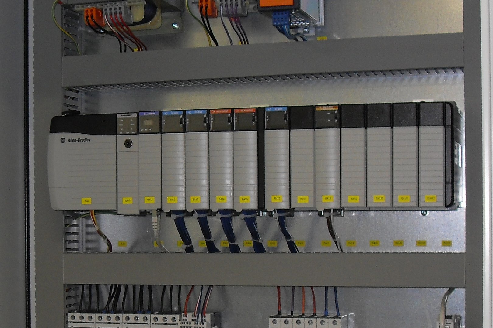 English: Allen Bradley PLC for a sugar centrifugal...
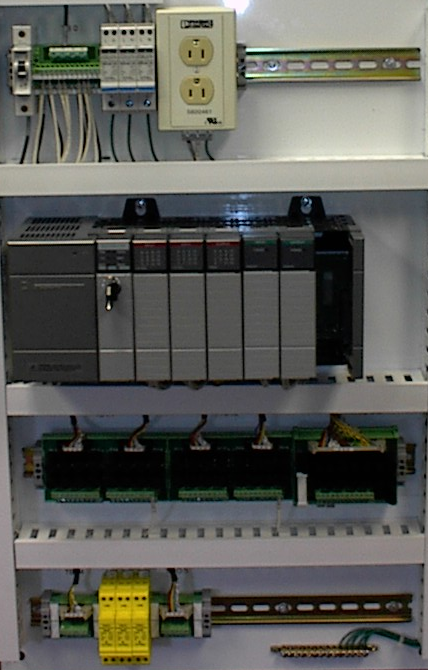 English: Made by me of a constructed panel with my...
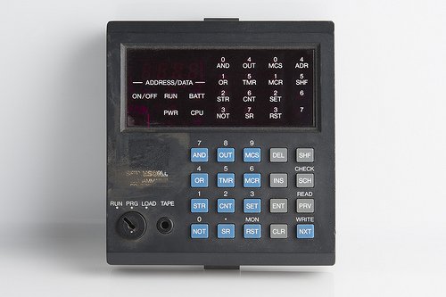 Blog Post Image
Relays are not a problem in the new designs, but most have been replaced in logic level controls units needing high current and high voltage switches. Most systems needing on and off switches control many units at one time, but these control systems are not usually made from electromechanical relays or logic gates. Instead digital computers are used, which can be programmed to do a lot of the logical functions.
In the late 1960's a company called Bedford Associates made a machine they called MODICON. It stood for modular digital controller, and became the name of a company that only worked on the design, making, and sales of these computers. Other companies made their own versions of this device, and it came as a PLC, or Programmable Logic Controller. The use of a PLC was to replace electromechanical relays as logic elements, and take the place of a solid state digital computer with a program, able to take the place of many relays.
Internal utility relays are not relays and are what makes a PLC remove outside relays. There are also some special relays that are made to perform only one job. Some are always on, and some are always off. Some are on only once during power up and are usually used to prepare the PLC to read the data that was stored.
Counters are virtual counters and they can be programmed to count pulses. Usually these counters can count up, down or both up and down at the same time. Since they are virtual they are limited in their counting speed. Some PLCs also have high speed counters that are on the hardware.
Timers come in many increments. The most usual type is an on delay type. Others have off delay and both retentive and non retentive types. Increments change from 1ms through 1s. Output relays are connected to everything else. They send on, off signals to solenoids, lights, and other units. They can be transistors, relays, or triacs based on witch PLC model you have.
Usually there is registers made to only store data. They are usually used as storage for math or data. They can also be used to store data when power is removed from the PLC. The next time the PLC cuts on they will have the same program as before power was cut off.
A PLC has many inputs, in which it takes high and low logical states from sensors and switches. It also has many outputs, in which it outputs high and low signals to control lights, solenoids, contactors, small motors, and other devices connected to on, off controls. To try to make PLCs easy to program, their programming language were made to look like ladder logic diagrams. So, an industrial electrician or electrical engineer used to reading ladder logic schematics could easley program a PLC.
PLCs are industrial computers, and their input and output signals are usually 120 volts AC, like the electromechanical control relays they were designed to replace. Although some PLCs can input and output low DC voltage signals in logic gate circuits. Signal connection and programming change a little from PLC to PLC, but they are similar enough overall to be taughtInside the PLC housing between each input terminal and Common terminal, is an opto-isolator device or light emitting diode that gives a single high logic signal to the computer's circuitry when there is 120 VAC power hooked up between the input terminal and the common terminal. A LED on the front panel of the PLC lets you know an input is being used.
Output signals are made by the PLC's computer circuitry when cutting on a switch, connecting the terminal to any of the output terminals. The source terminal is usually connected to the side of the 120 VAC power source. By doing this the PLC is able to work with real world devices such as switches and solenoids.
The actual logic of the control system is accepted inside the PLC by a computer program. This program controls which output gets used under input settings. Although the program looks like ladder logic diagram, with switch and relay symbols, there are no switch contacts or relay coils working inside the PLC.
ItÃÂs important to know that the personal computer used to show and edit the PLC's program is not necessary for the PLC's operation. Once a program has been put into the PLC from the personal computer, the personal computer may be unplugged from the PLC, and the PLC will still follow the programmed commands.
The power and use of a PLC is shown when you want to change the actions of a control system. Since the PLC is a programmable device, you can change its actions by changing its commands it is given, without having to change the electrical components connected to it. One advantage of PLCs is that they cannot be replaced by electromechanical relays. Because a PLC is a special purpose digital computer, it has the ability to hook up with other computers easilyAt Lanier Technical College you have to first get your Industrial Mechanical Technician Certificate before you can get your Programmable Logic Controllers Technician Certificate. To get your Mechanical Technician Certificate you have to take and pass Industrial Mechanics, Maintenance for Reliability Industrial Fluid power, and Pumps and Piping Systems. The average cost of this course per quarter is $1,192, and it usually takes two quarters to finish.
To get your Programmable Logic Controllers Technician Certificate you need to take and pass Fund of Motor Controls, Basic Industrial PLCs, Industrial PLCs, and Industrial Safety Procedures. The average cost of this course per quarter is $1,042, and it usually takes two quarters to finish.
To apply to Lanier Technical College you must be at least 16 years old, submit application with a nonrefundable $15 application fee, and take the ASSET test or submit SAT, ACT, CPE or COMPASS test scores. All tests must have been taken within five years of application for admission.
Programmable Logic Controllers Technicians make from $50,000 to $75,000 a year with less than one year of experience. There are many job opportunities for Programmable Logic Controllers Technicians in Atlanta, and in the south east.
Cite: Wikipedia, yahoo.com. answers.com, PLC.com
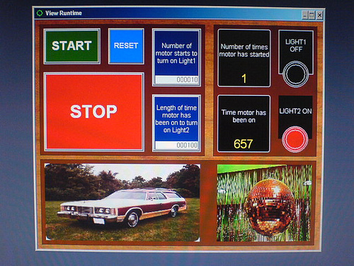 1970's Themed PLC HMI
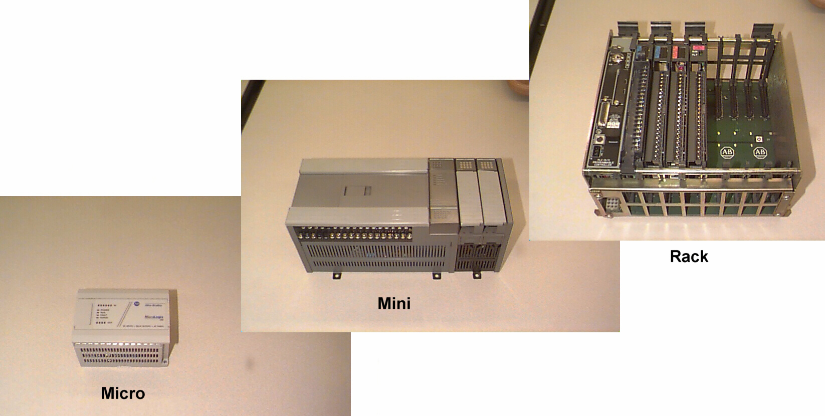 PLC
PLC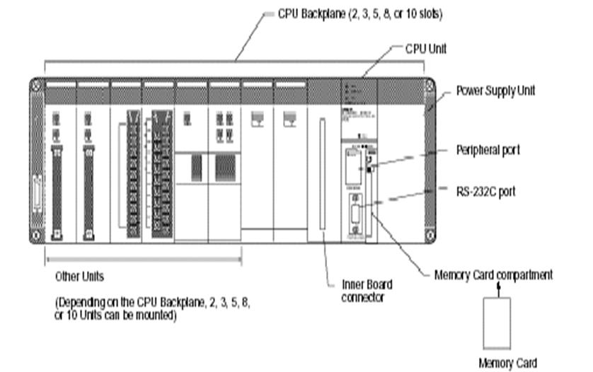 PLC's HardWare