Introduction
The purpose of the experiment is that of examining a half and full wave rectifier circuit by recording and comparing the results of each circuit:
÷Without a smoothing capacitor
÷With a smoothing capacitor
To record the results on the ripple voltage by :
÷Using different values of smoothing capacitors
÷Varying the load current conditions
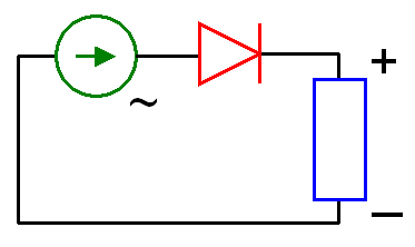
Theory Of Half Wave Rectifier Circuit
The half wave circuit is so called because current flows through the diode only for that half of the AC wave, which is in the forward direction. The output waveform therefore consists of the positive half of the sine wave only (Fig 1), with the result that the output circuit although flowing in one direction only, is not smooth DC.
By connecting a DC meter across the load resistor in the half wave rectifier circuit the recorded voltage will be less than half that of the r.m.s. (root mean square) value of the AC voltage applied to the rectifier.
 Half-wave rectifier
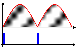 Load voltage regulated by thyristor phase control....
 Full-wave rectifier
Fig 1 Half Wave Rectifier Circuit
By selecting a suitably large value of capacitor, current flow through the load resistance can be made continuous rather than coming in half wave bursts. The smoothing capacitor will store some electric charge while the diode is conducting; this releases this charge to provide current flow while the diode is not conducting. (Fig 1b).
Fig 1b Full wave rectifier circuit with smoothing
Theory of Full Wave Rectifier Circuit
Fig2 shows a full wave rectifier connected to a centre tapped transformer. Using a centre tap earthed, the AC voltage ate each end of the secondary of the transformer will be balanced above zero i.e. when the voltage at A is at its positive peak, the voltage at B will be at its negative peak and vice versa.
When the winding end marked A is positive,
Comment
would be much more helpful if figures could be viewed!
1 out of 1 people found this comment useful.