Title: Resistors in Series and Parallel
Date: 17/7/05
Aim:
The aim of this experiment is to compare the predicted and actual resistance in a circuit of resistor combinations in series and in parallel.
Background:
A resistor is an electrical component/device that has electrical resistance. Resistors can be used in electric circuits for protection of components, voltage division or current control. In an ideal resistor the resistance remains constant regardless of the applied voltage or current, or the rate of change in the current (Resistor, 2005, Wikipedia).
Electrical resistance is a measure of the ability of an object to oppose the passage of an electric current. The electrical resistance of an electrical component can be found by using Ohm's law. Ohm's law states that the potential difference (voltage) between the ends of a conductor (e.g. a resistor) and the current flowing through the conductor are proportional at a given temperature (Storen & Martine, 2000, p221-226).
 Three electrical resistors.
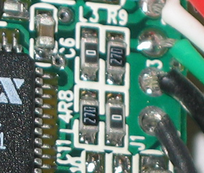 This photo shows some surface mounted resistors, i...
 resistor
This law can be written as: R=V .
I
The SI unit used for electrical resistance is an ohm. An electrical device that has an electrical resistance of 1 ohm will cause a current of 1 amp to flow through it if a voltage of 1V is passed through it.
From previous scientific research it has been determined that the general law for resistors in series is: Rseries = R1 + R2 + R3+Rn
It has also been determined that the general law for resistors in parallel is
Rparallel =
Hypothesis:
From the formulas stated in the Background of this report it can be seen that the total resistance of resistors in series can be found by adding together the individual resistances of each component. It can also be seen that the total resistance of resistors in parallel can be found by adding together the...