Theory of Operation
One common requirement in digital circuits is counting, both forward and backward. Digital clocks and watches are everywhere, timers are found in a range of appliances from microwave ovens to VCRs.
This circuit is used as a counter. The two 7-segment displays (1 least significant digit, and 1 most significant digit) count up (LSD = 1/10 sec, MSD = 1/100 sec). The least significant digit's output (carry out) feeds into the most significant digit input.
1. 555 monostable multivibrator creates 320Hz.
Monostable multivibrator often called a one shot multivibrator is a pulse generating circuit in which the duration of this pulse is determined by the RC network connected externally to the 555 timer. In a stable or standby state, the output of the circuit is approximately zero or a logic-low level. When external trigger pulse is applied output is forced to go high (VCC). The time for which output remains high is determined by the external RC network connected to the timer.
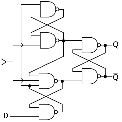 A positive-edge-triggered D flip-flop
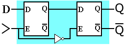 A master–slave D flip-flop. It responds on the n...
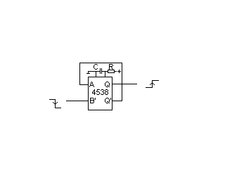 English: Monostable multivibrator
At the end of the timing interval, the output automatically reverts back to its logic-low stable state. The output stays low until trigger pulse is again applied. Then the cycle repeats. The monostable circuit has only one stable state (output low) hence the name monostable.
2. 7474 D flip-flop divides the 320Hz by 2 (divide by two)
The D flip-flop tracks the input, making transitions with match those of the input D. The D stands for "data"; this flip-flop stores the value that is on the data line. It can be thought of as a basic memory cell.
3. The clocks to all circuits run off the Q output of the 555
4. A 74163 SN74163 Synchronous Programmable Hex Counter divides the 160Hz to 16Hz by using a divide by ratio of 13 and...