High Level Shading Language (HLSL), a programming language for Graphic Processing Unit (GPU) in DirectX 9.0, supports the shader construction with C-like syntax, types, expressions, statements, and functions.
Long time ago, Apple's RenderMan was a popular shading language that was used to generate cinematic effects with CPU in render farms. Lately, Microsoft's HLSL and OpenGL's GLSLang have been developed for real-time shaders on GPU. Best integrated into the DirectX 9.0, HLSL works solely on Windows platform. Similarly, OpenGL 1.5 starts to include OpenGL shading language GLSLang as a standard component. These high level languages accerlate the development of shaders.
To build a complete shader, new shading languages for GPU must work along with a host programming language such as C++, which is tedious to set large amount of parameters. Neatware's Media Control Lnaguage (mCL) supports High- Level Shading Languages (HLSL) and DirectX 9. Shader writers can easily embeded HLSL into a mCL function, modify parameters of a shader, and compose with other media.
 HLSL
HLSL Xiangqi-hlsl
 OpenGL Shading Language, Second Edition
Simplest Example A shader is consists of vertex shader and pixel shader. The stream of 3D model flows from application to the vertex shader, then to the pixel shader, finally to the frame buffer. a2v struct represents the data structure transfered from an appliction to a vertex shader, v2p from a vertex shader to a pixel shader, and p2f from a pixel shader to the frame buffer. Below program transforms a vertex's position into the position of clip space by view matrix.
inline hlsl_example { struct a2v { float4 Position : POSITION; }; inline, a mCL command, defines the HLSL source code with the name hlsl_example. Inside the HLSL function, struct a2v specifies a vertex structure that represents the data of a vertice.
struct v2p { float4 Position : POSITION; }; struct a2v specifies a stream structure from vertex to pixel shader. Position is a four dimentional vector declared by float4. Furthermore, POSITION, called output semantic, indicates the initialized type of Position.
void main(in a2v IN, out v2p OUT, uniform float4x4 ModelViewMatrix) { OUT.Position = mul(IN.Position, ModelViewMatrix); } } main is a vertex shader function name. void means that this function will return nothing. The input parameter IN is specified by in modifier and struct a2v. Similarly, the output parameter OUT is specified by out modifier with the type v2p. In addition, float4x4 declares a matrix ModelViewMatrix. The uniform modifier indicates that the value of the matrix is a constant assigned by external program. Finally, this simplest vertex shader outputs the multiplication of the vector Position and the matrix ModelViewMatrix. While IN.Position is the left parameter of mul, it is considered as a row vector. Otherwise it is considered as a column vector.
HLSL provides scalar data type like float and vector data type like float3. The scalar data types include bool with true or false value, int with 32-bit signed integer value, half with 16-bit floating point value, float with 32-bit floating point value, and double with 64-bit floating point value. An emulation will work while a GPU does not support a data type.
A vector data type is declared as vector where size is the dimension and type is the scalar component type. vector is a declaration of 4 dimensional float vector. Usually, I use float2, float3, and float4 for two, three, and four dimensional float vectors.
float4x4 declares a float matrix type with 4 rows and 4 cols. A general matrix declaration has the form matrix. A varity of dimensional declaration such as float3x4 is also acceptable. To access an element of matrix you can use m[i][j] or zero-based row-column position like _m00 as well as one-based row-column position like _11.
You can think HLSL as a C language for GPU programming except there are no pointer, union, bitwise operations, and function variables. There are no goto, switch, recursive function in HLSL as well. However HLSL addes vector data type, build-in constructor, swizzling and masking operators. HLSL standard library includes mathmatical functions and texture processing functions. The function overloading has been used to unify the operations of different vectors.
inline asm_example { vs_1_1 dcl_position v0 m4x4 oPos, v0, c0 mov oD0, c4 } This asm program is the compiled code of the simplest HLSL example. First, vs_1_1 specifies the version of vertex shader as 1.1. Second, dcl_position v0 declares that v0 is a position register. The third statement declares a matrix multiply with source variable register v0 and constant register c0 where oPos represents the destination position register. Finally, the last statement moves the value of register c4 to register oD0. Usually, vN represents input register and oXXX represents output register in the assembly vertex shader language.
Add Diffuse Color In this example I add COLOR component as the diffuse color.
inline hlsl_plane { struct a2v { float4 Position : POSITION; float4 Color : COLOR0; }; a2v structure declares the data structure transfered from application vertex shader. Note POSITION and COLOR0 are input semantics that link the vertex buffer of the application to the vertex shader. Vertex shader input semantics include POSITIONn for Position, BLENDWEIGHTn for Blend weights, BLENDINDICESn for Blend indices, NORMALn for Normal vector, PSIZEn for Point size, COLORn for Color, TEXCOORDn for Texture coordinates, TANGENTn for Tangent, BINORMALn for Binormal, and TESSFACTORn for Tessellation factor.
struct v2p { float4 Position : POSITION; float4 Color : COLOR0; }; v2p structure declares the data structure transfered from vertex shader to pixel shader. Vertex shader output semantics include POSITION for Position, PSIZE for Point size, FOG for Vertex fog, COLORn for Color, and TEXCOORDn for texture coordinates.
void main(in a2v IN, out v2p OUT, uniform float4x4 ModelViewMatrix) { OUT.Position = mul(IN.Position, ModelViewMatrix); OUT.Color = IN.Color; } } In this example Color component specifies the diffuse color from application. It simply copies the Color from the IN to OUT in the main function.
Diffuse and Specular This is a little bit more complicated example shown the implementation of diffuse and specular color.
inline hlsl_plane { struct a2v { float4 Position : POSITION; float4 Normal : NORMAL; }; Normal item is added for color computing.
struct v2p { float4 Position : POSITION; float4 Color : COLOR0; }; color outputs to pixel shader.
void main(in a2v IN, out v2p OUT, uniform float4x4 ModelViewProj, uniform float4x4 ModelViewIT, uniform float4 LightVec) { input parameters include view project matrix ModelViewProj, view inverse transpose matrix ModelViewIT, and light vector LightVec.
OUT.Position = mul(IN.Position, ModelViewProj); multiply position with view project matrix float4 normal = normalize(mul(IN.Normal, ModelViewIT).xyzz); float4 light = normalize(LightVec); float4 eye = float4(1.0, 1.0, 1.0, 0.0); float4 vhalf = normalize(light + eye); transform normal from model-space to view-space, store normalized light vector, and calculate half angle vector. float4(1.0, 1.0, 1.0, 0.0) is a vector constructor to initialize vector float4 eye.
.xyzz, a swizzle operator, sets the last component w as the z value.
float diffuse = dot(normal, light); float specular = dot(normal, vhalf); specular = pow(specular, 32); calculate diffuse and specular components with dot product and pow function.
float4 diffuseMaterial = float4(0.5, 0.5, 1.0, 1.0); float4 specularMaterial = float4(0.5, 0.5, 1.0, 1.0); set diffuse and specular material.
OUT.Color = diffuse * diffuseMaterial + specular * specularMaterial; } } add diffuse and specular components and output final vertex color.
To better understand a swizzle operator, readers can compare cross definition float3 cross( float3 a, float3 b ) { return float3( a.y*b.z - a.z*b.y, a.z*b.x - a.x*b.z, a.z*b.y - a.y*b.z ); } and its swizzle implementation float3 cross( float3 a, float3 b ) { return a.yzx*b.zxy - a.zxy*b.yzx; } Paint Texture Now I are going to show how to add texture on a surface inline hlsl_plane { struct a2v { float4 Position : POSITION; float2 Texcoord : TEXCOORD0; float4 Normal : NORMAL; }; add new Texcoord component as texture coordinate with TEXCOORD0.
struct v2p { float4 Position : POSITION; float2 Texcoord : TEXCOORD0; float4 Color : COLOR0; }; add Texcoord in output void main(in a2v IN, out v2p OUT, uniform float4x4 ModelViewProj, uniform float4x4 ModelViewIT, uniform float4 LightVec) { OUT.Position = mul(IN.Position, ModelViewProj); ... same as the above example set texture coord OUT.Texcoord = IN.Texcoord; } } the code is the same as the above example except that the texture coord copy is added.
Pixel Shader Pixel shader completes the computing of pixels.
inline hlsl_pixel_plane { struct v2p { float4 Position : POSITION; float2 Texcoord0 : TEXCOORD0; float2 Texcoord1 : TEXCOORD1; float4 Color : COLOR0; }; v2p declares a struct type that transfers data from vertex shader to pixel shader. It is the same as the struct in vertex shader. The input semantics of pixel shader can be COLORn for Color or TEXCOORDn for Texture coordinates. Although the struct v2p must be the same as the v2p in the vertex shader, the item Position can not be read in the pixel shader, because it is not binded by the input semantics of the pixel shader.
struct p2f { float4 Color : COLOR0; }; p2f declares output data structure and OUT is the output object. The output semantics of pixel shader can be COLORn of Color for render target n and/or DEPTH for Depth value.
void main(in v2p IN, out p2f OUT, uniform float brightness, uniform sampler2D tex0, uniform sampler2D tex1) { Constant parameter brightness has a float type. sampler2D specifies a 2D texture unit. When you plan to access a texture you must use sampler with an intrinsic function. A sampler can be used for multiple times.
float4 color = tex2D(tex0, IN.Texcoord0); float4 bump = tex2D(tex1, IN.Texcoord1); fetch texture color and bump coordinate for further computing of bump effect. tex2D is an texture sampling intrinsic function of HLSL. It generates a vector from a texture sampler and a texture coordinate.
OUT.Color = brightness * IN.Color * color; } } the code multiples brightness, IN.Color and color to generate output RGBA color vector.
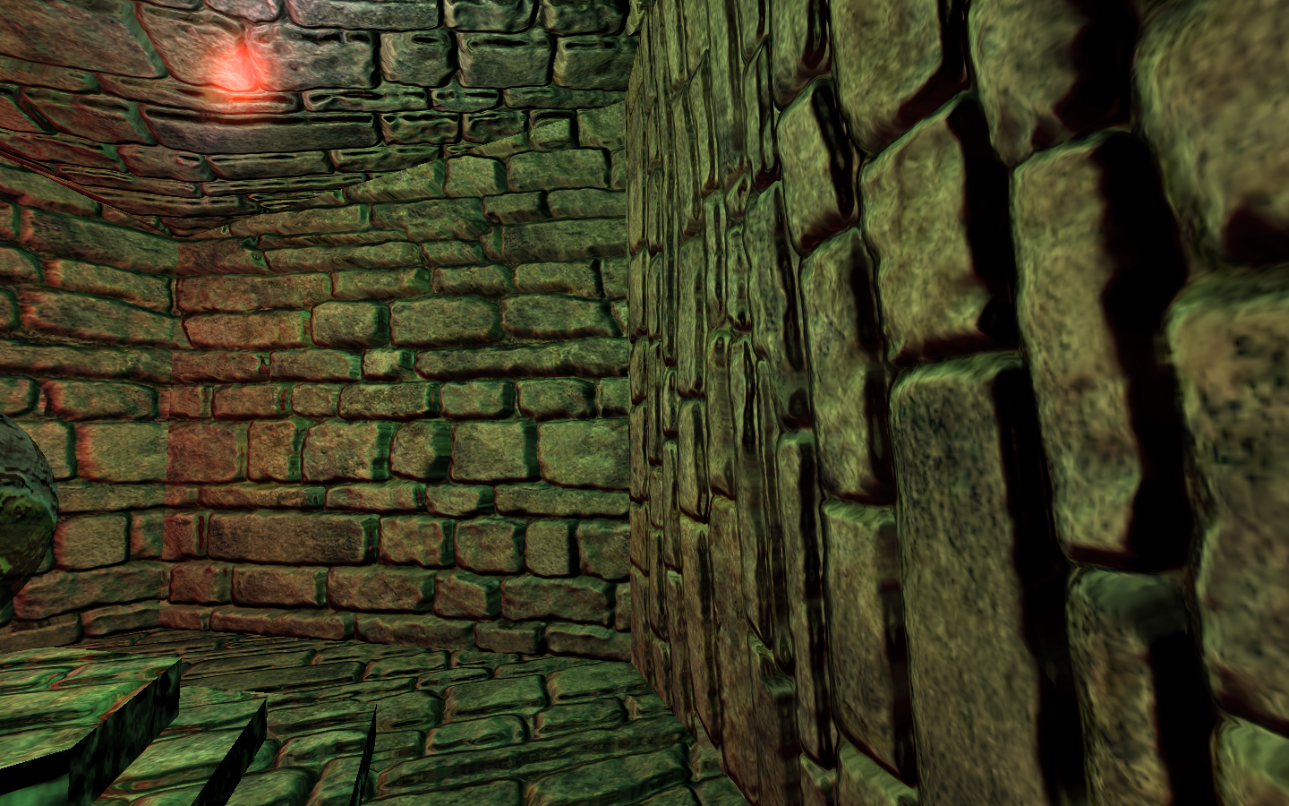
Bumpmapping and Per-Pixel Lighting float4 light = normalize(posWorld-vLight); float4 eye = normalize(vEye-light); float4 vhalf = normalize(eye-vLight); transform light and vhalf vectors to tangent space float3 L = float3(dot(tangent, light), dot(binormal, light.xyz), dot(normal, light)); float3 H = float3(dot(tangent, vhalf), dot(binormal, vhalf.xyz), dot(normal, vhalf)); calculate diffuse and specular components float diffuse = dot(normal, L); float specular = dot(normal, H); specular = pow(specular, power); combine diffuse and specular contributions and output final vertex color, set texture coordinates, and return output object.
OUT.Color = 2.0*(diffuse*vDiffuseMaterial + specular*vSpecularMaterial) + 0.5 + vAmbient; OUT.Texcoord0 = IN.Texcoord; OUT.Texcoord1 = IN.Texcoord; } } Pixel Shader for Image Processing This program shows the implementation of Sobel edge filter with a HLSL pixel shader. In the similar way I can implement many image filters in pixel shaders along with the mCL programs.
inline hlsl_pixel_edge { struct v2p { float4 Position : POSITION; float2 Texcoord : TEXCOORD0; float4 Color : COLOR0; }; struct p2f { float4 Color : COLOR0; }; main function includes a vertice struct as input, a float parameter as brightness control, and a 2D texture sampler. The return value has float4 type with the semantic COLOR0.
void main( in v2p IN, out p2f OUT, uniform float Brightness, uniform sampler2D tex0 ) { const specifies the constants. The c[NUM] is a float2 constant array. Notes its initialization is convenience like C language. col[NUM] is a variable array of type float3 with NUM elements. int i declares the i as integer. These useage is effective for pixel shader 2.0 or later.
const int NUM = 9; const float threshold = 0.05; const float2 c[NUM] = { float2(-0.0078125, 0.0078125), float2( 0.00 , 0.0078125), float2( 0.0078125, 0.0078125), float2(-0.0078125, 0.00 ), float2( 0.0, 0.0), float2( 0.0078125, 0.007 ), float2(-0.0078125,-0.0078125), float2( 0.00 , -0.0078125), float2( 0.0078125,-0.0078125), }; float3 col[NUM]; int i; it stores the samples of texture to col array.
for (i=0; i < NUM; i++) { col[i] = tex2D(tex0, IN.Texcoord.xy + c[i]); } now I start to compute the luminance with dot product and store them in lum array.
float3 rgb2lum = float3(0.30, 0.59, 0.11); float lum[NUM]; for (i = 0; i < NUM; i++) { lum[i] = dot(col[i].xyz, rgb2lum); } Sobel filter computes new value at the central position by sum the weighted neighbors.
float x = lum[2]+ lum[8]+2*lum[5]-lum[0]-2*lum[3]-lum[6]; float y = lum[6]+2*lum[7]+ lum[8]-lum[0]-2*lum[1]-lum[2]; show the points which values are over the threshold and hide others. Final result is the product of col[5] and edge detector value. Brightness adjust the brightness of the image.
float edge =(x*x + y*y < threshold)? 1.0:0.0; final output OUT.xyz = Brightness * col[5].xyz * edge.xxx; OUT.w = 1.0; } }
 This is a demo of realtime dynamic glass refractio...
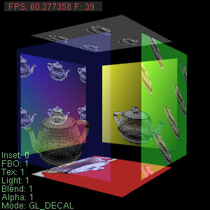 Author: Bob Free (bfree@graphcomp.com) May be used...
 English: 6600GT GPU