Objective:
In this experiment, we are aiming to determine the Joule Thomson coefficient ( ) of CO2 and N2 gases.
Equipments:
Joule-Thomson apparatus, digital temperature meter, two temperature probes. Two vacuum rubbers tubing, reduce valves for CO2 and N2 two steel cylinders for CO2 and N2 gases, 10 liters capacity each.
Theory:
In real gases, the internal energy U is composed of a thermo kinetic content : the potential of the intermolecular forces of attraction. This is negative and tends towards zero as the molecular distance increases. In real gases, the internal energy is therefore a function of the volume while the internal energy for ideal gas is a function of temperature only and hence:
During adiabatic expansion ( and during which also no external work done, the overall internal energy remains unchanged, with the result that potential energy increases at the expanses of the thermo-kinetic content and the gas cools.
H1=U1+P1V1=U2+P2+V2=H2
In this equation, PV is the work performed by an imaginary piston during the flow of a small amount of gas by a change in piston 1 to 2 or piston 3 to 4 (Fig-2).
In real gases, the displacement work PV does not equal to the displacement work equal the displacement work P V: in this case: P1V1 P2V2
Procedure:
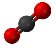 ball-and-stick model of CO2: carbon dioxide
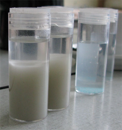 English: Liquid CO2 at room temperature, produced ...
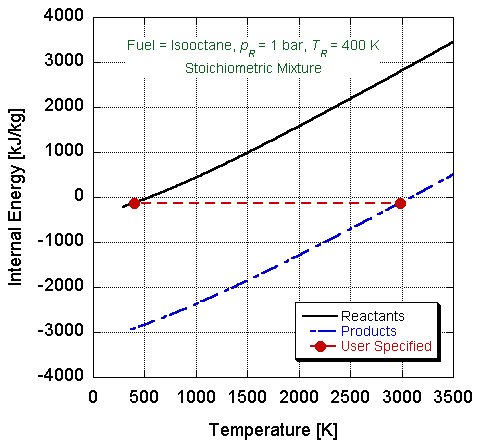 Internal energy versus temperature diagram illustr...
First of all , the reducing valves of the steel cylinder area screwed and the main valves tightness area checked too. The steel cylinders are put on a secure location. The vacuum between the reducing valve and the Joule-Thomson apparatus is attached with hose tube clips. A temperature probe on the un-pressurized side to inlet 2 of the temperature measurements apparatus.
Results:
P | N2 | CO2 |
1 | 0 | 0.52 |
0.9 | -0.005 | 0.49 |
0.8 | -0.015 | 0.46 |
0.7 | -0.013 | 0.42 |
0.6 | -0.015 | 0.39 |
0.5 | -0.017 | 0.31 |
0.4 | -0.024 | 0.24 |
0.3 | -0.025 | 0.15 |
0.2 | -0.026 | 0.08 |
0.1 | -0.028 | 0.01 |
0 | -0.032 | 0 |
Graph:
P (bar) | |
0 | 0 |
0.9 | 0.09 |
0.8 | 0.13 |
0.7 | 0.16 |
0.6 | 0.22 |
0.5 | 0.24 |
0.4 | 0.27 |
0.3 | 0.3 |
0.2 | 0.33 |
0.1 | 0.4 |
0 | 0.43 |
Calculations:
From the slope equation in the graph we get:
Y= 7 * 106 -0.0614 for CO2 y= 7 * 10-7 X-0.2364 for N2
Y=mx +c y=mx+c
Slope = 7 * 10-6- Slope = 7 * 10-7
Therefore,
õJT = 7 * 10-7 K\Pa for N2
õJT = 7 * 10-6- K\Pa for CO2
Van Der Waals
-For Co2
= 9.43 * 10-4 K/Pa
-For N2
=-7.4 * 10-3 K/Pa
The literature value for CO2: is õCO2= 1.16 * 10 -5 K/Pa
The literature valve for N2 : is õN2=
Co2:
Experimental value VS. Literature valve
7*10 -6 K/Pa Vs 1.16 * 105 K/Pa
=
= 39.6 %
N2:
Experimental value Vs Literature value
7* 10-7 K/Pa Vs 1.16 * 10-5 K/Pa
= * 100
= 72 %
Conclusion:-
From this experiment we can determine the Joule Thomson coefficient ( õ) of CO2 and N2 gases. Also The experimenting room and the experimental apparatus
Must be in a thermal equilibrium at the start of the measurement.
The experimental apparatus should be kept out of direct
Sunlight and other sources of heating or cooling.