Introduction
The purpose of this lab is to investigate the nature, position, and size of images formed by a converging lens.
If the lens is at the focal point, then the image will be inverted because the image will be real but not visible.
Procedures
1. Collect the converging lens, lens holder, the meter stick, the meter stick holders, the note card, and the night-light with a clear, 7-watt bulb.
2. Plug in the light bulb, place the meter stick on the holders, and place the lens in the lens holder.
3. Set up the lens onto the meter stick, and place the note card at the end of the meter stick.
4. Slowly move the lens back and forth to find the focal point, at which the image will be inverted and clear.
5. Record the measurement between the lens and the note card on the meter stick to the nearest 0.1
 Photosynth 360-degree Panorama virtual image at Va...
 English: Center point tower in Market st Sydney. I...
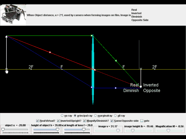 English: Ejs open source converging & diverging Le...
cm. Record the number of your lens.
6. Locate the position of the image on a ray-diagram. Draw the path of the ray that leaves the tip of the arrow parallel to the principal axis.
7. Use the ray-diagram to locate the image of the object in Figure c. Draw the path of the ray that leaves the tip of the arrow parallel to the principal axis and is refracted by the lens. Trace another ray that heads toward the lens in the same direction as if it was originated from the focal point and refracted by the lens.
8. Move the light source further away and again record the focal length.
9. When the position of the object is at, beyond, and within the focal points, record whether the images are real or virtual, magnified, and inverted or erect, and record in a table.
10. Again, locate the position of the image in figure be using a ray diagram.
11. Use a ray diagram to locate the image of the object in figure C.
Observations/Results/Analysis
Focal Length= 18 cm
Lens number= ÃÂ
Light further away focal length- 10 cm
Position of Object Real/Virtual? Magnified? Inverted or Erect?
Beyond f Real Yes Inverted
At f Real No Both
Within f Virtual No Erect
Ray Diagrams
Fig B
Fig C
Analysis
2. Where does this ray go after it is refracted?
The ray goes towards and through the focal point.
3. Where does this light ray go after it is refracted?
The ray goes parallel to the principal axis.
4. Do the refracted rays actually cross?
No they do not actually cross.
5. Where do they appear to cross?
Where the object is.
6. Could the image be projected onto a screen?
Yes it could be projected onto a screen.
At what distance does the letter appear to be upright?
The letter appears upright when the lens is within the focal point.
In what distance range does the image appear to be upside down?
When the lens is beyond the focal length.
At which distance is the image of the letter completely gone?
When the lens is precisely at the focal point.
Conclusion
In this experiment we discovered that when placed at different lengths from a light source, a lens will refract light in different ways. When a lens is inside the focal length it creates a virtual image that is erect and magnified, but unable to be projected onto a screen, but when a lens is outside of a focal length, the image created will be real, upside down, and able to be projected on the screen. Sources of error in this experiment could include incorrect measurement, a flawed lens or light bulb maybe, and differing vision. The information we discovered supported our hypothesis because when the lens was at its focal point, the image was inverted but not visible. The most fallible areas most likely to cause measurable experimental error are that the human eye cannot detect when the lens is perfectly at the focal point, which would also lead to measurement errors. This could have changed the focal length, therefore altering the rest of our results.