ELE 3330 Laboratory Experiment: Microstrip Antenna Analysis and Measurement Lee Sim Heung (Student ID: 0065 4331) Yam Chun Kit (Student ID: 0075 8792) Date of Experiment: 12th March 2002 Objective Analyze the microstrip antennas by the transmission line model. Measure the resonant frequency and antenna gain of a microstrip antenna.
Introduction Microstrip antenna has advantages that small size, light weight, simple and inexpensive to manufacture. It can be used in aircraft, satellite application, mobile radio and wireless communication system. Rectangular Microstrip Antenna is the most widely used configuration. The transmission line modeling of a rectangular microstrip antenna will be applied in this experiment. In addition, the measurement of the resonant frequency and antenna gain will be introduced.
The transmission line model is the easiest of all. The rectangular microstrip antenna can be represented as an array of two radiating slots separated by a low-impedance transmission line of length L.
The resonant frequency of an antenna is determined by its input impedance and the characteristic impedance of the interconnecting transmission line.
 A girl on a garden swing. Original caption: : Binc...
 English: "Resonance effect shown for various input...
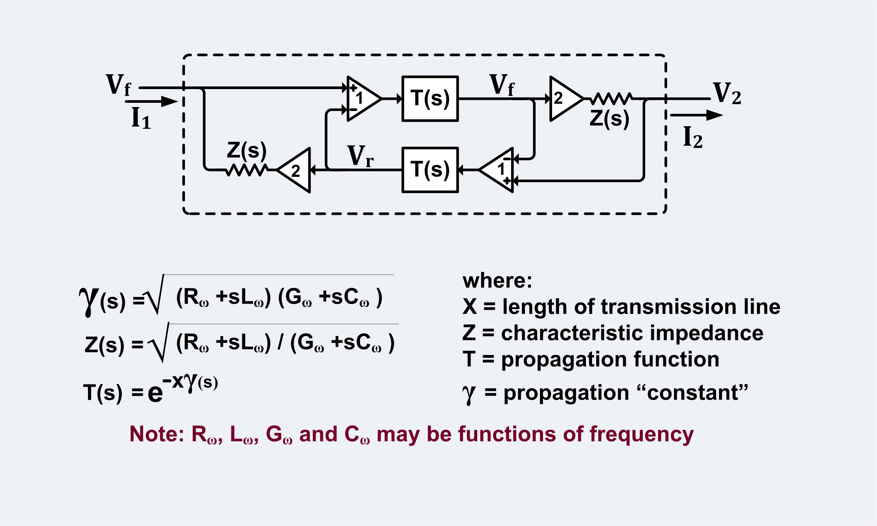 English: A circuit that has the same response as a...
Input impedance of an antenna represents the ratio of the voltage to current at its terminals, it is generally a function of frequency. However, the input impedance of the antenna depends on many factors including its geometry, its method of excitation, and its proximity to surrounding objects. Due to these complex geometries, the input impedance usually determined experimentally.
The antenna gain is usually defined with reference to an isotropic radiator. With reference to an isotropic radiator antenna gain G is defined as: where Pa = power density radiated by the antenna in a given direction, Pi = power density radiated by an isotropic radiator.
Procedures Part A Reflection coefficient of Antenna 1) Connect Rectangular Microstrip Antenna to Network Analyzer. Measure the reflection coefficient of the Patch Antenna.
2) Find the resonant frequency of the antenna Part B Resonant frequency of Antenna 1) Setup the apparatus shown on Figure 1.
2) With 100MHz stepping frequency, measure the received power from operation frequency 2.5GHz to 3.2GHz.
3) Comment on the result, find the resonant frequency of the antenna and compare the result with Part (A).
4) Comment on the procedure of finding the resonant frequency of antenna between Part (A) and (B).
Part C Rectangular Microstrip Antenna Analysis Given that the width of the rectangular microstrip antenna in the previous part is 65.7mm, height is 1mm, dielectric constant is 2.17, based on the resonant frequency measured, calculate the actual length and the effective length of the patch by using transmission-line model.
Part D Antenna gain measurement 1) From the result of Part (B), choose the best operating frequency of the Rectangular Microstrip Antenna use the frequency in this part.
2) Varying the distance r between the Transmitter and Receiver. Measure the received power with r = 2m, 1.5m and 1m.
3) Comment on your results.
Result and Discussion Part A Find the resonant frequency of the antenna: Reflection coefficient ãFin = -13.175dB Resonant frequency of the antenna is 2.98GHz @ 3.0GHz Part B Frequency (GHz) Received Power (dBm) 2.5 -62.5 2.6 -59 2.7 -55 2.8 -49 2.9 -36.5 3.0 -31.9 3.1 -46.9 3.2 -46 From table, we can see that the maximum received power is áV31.9 dBm. Thus the resonant frequency is 3GHz.
Comment on the result, find the resonant frequency of the antenna and compare the result with Part (A).
The result is similar to the result in Part A.
Comment on the procedure of finding the resonant frequency of antenna between Part (A) and (B).
In Part A, we measure the resonant frequency by Network Analyzer directly, so the result is more accurate and less affect from the surrounding. But in Part B, we measure the signal by a receiver, thus some large scale effect will involve, such as multi-path effect. Besides, the power loss of signal is much greater than Part A, due to the cables length. We can see that the value from signal generator is much larger than the actual power output. In addition, that two antennas may not be linear and exactly face each other, therefore the signal transmission may not travel in direct path.
P.S. reference picture showing multi-path effect.
Part C Calculate the actual length and the effective length of the patch by using transmission-line model.(for er = 2.17, h = 1mm, w = 65.7mm) By static áV TEM mode assumption: if w/h > 1 = 2.123 By E.O. Hammerstad, = 0.531 i.e. Effective length = 0.0343m = 34.3mm Actual length L = 33.25mm Part D Input power: 0dBm Operating Frequency: 3GHz Distance (r/m) Received Power (dBm) 2 -39 1.5 -37.5 1 -34.5 Distance (r/m) Input Power (dBm) Effective Input Power Received Power (dBm) Gt Gr(dB) Gt Gr Gt = Gr(dB) Gt = Gr 2 0 -4.9dBm -39 13.9048 24.57433365 6.9524 5 1.5 0 -4.9dBm -37.5 12.9060 19.52559502 6.4530 4.4 1 0 -4.9dBm -34.5 12.3842 17.31497063 6.1921 4.2 For two identical antennas, we can assume that Gt = Gr, thus from the above data, the gain of antenna is about 5.
Comment on results, Firstly, the number of samples is only 3, so it is quite difficult to find out the precise value of the gain.
In addition, the above equation is only valid for free space model with LOS, therefore it must occur some error if we use this for gain calculation.
Besides, the values of received power may have errors due to incorrect placing angle of antennas.
Extra part Direct connection through the cables: Input:-10 dBm Output: -14.9 dBm Loss = 4.9 dB ~~THE END~~
 English: A dipmeter measuring the self-resonant fr...
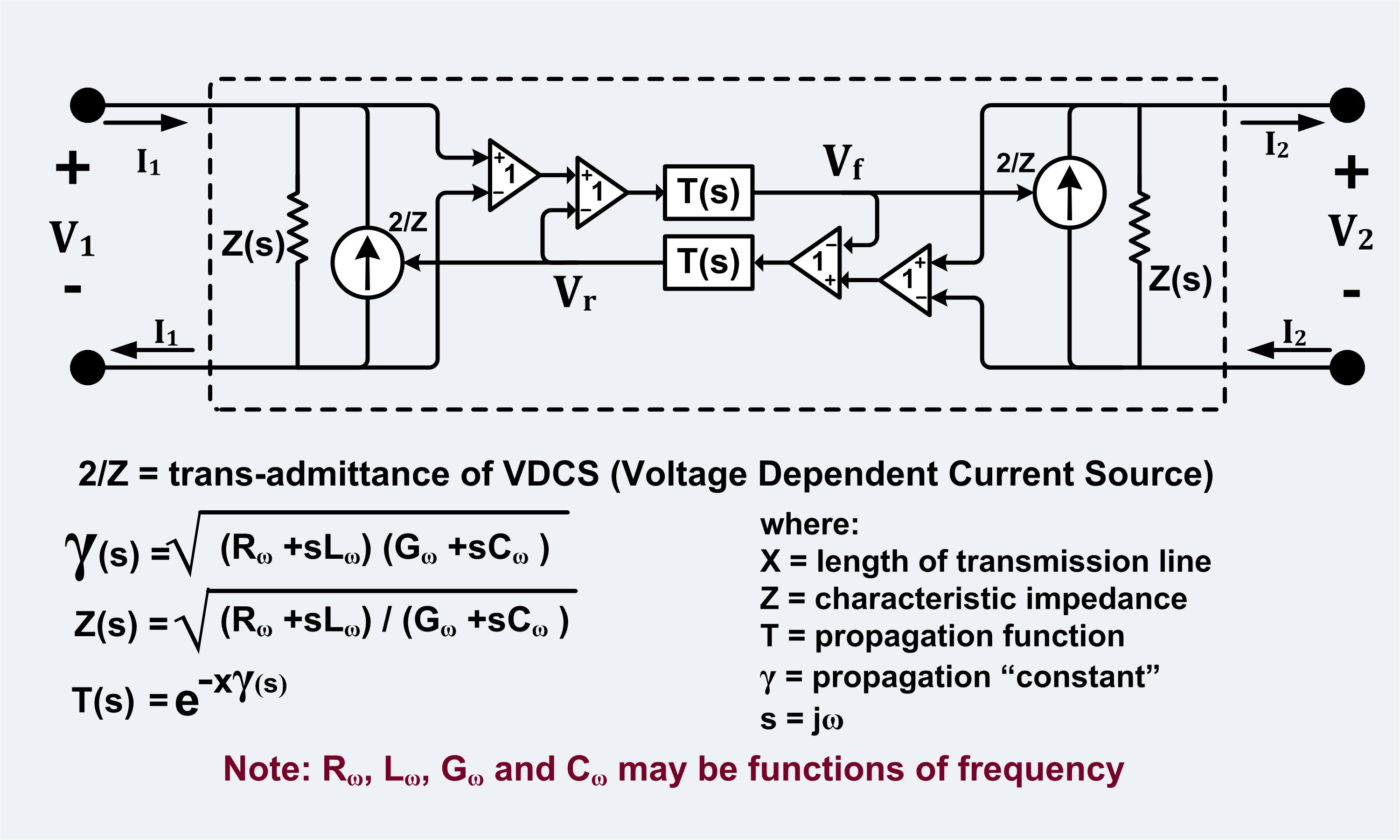 English: A circuit that produces the same response...
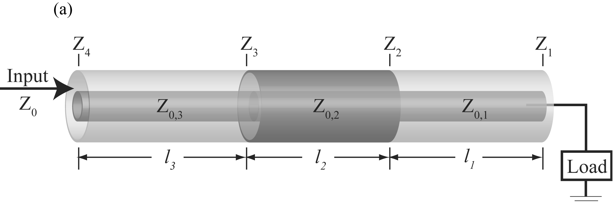 English: Stepped transmission line
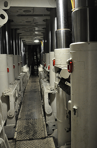 Powered roof supports, coal mining, DBM, Bochum
 HS-DBM