FROM: Team Delta
DATE: 4/20/05
SUBJECT: Ammonia Cooling Heat Exchanger Replacement
ATTACHMENTS: Calculations & Diagram
A need has risen to replace the existing heat exchanger (1) for cooling ammonia vapor exiting the ammonia converter (2). In response to this need, Team Delta has designed a new system for cooling the ammonia vapor using two vertical double pipe heat exchangers, and a pump for circulating the fluid. Because the cooling water used in the heat exchanger cannot be heated above 50 oC, an intermediate coolant, MultiTherm IG-4, will be used. Cooling water will be used to cool the MultiTherm, hence the need for two exchangers. A pump was sized for the appropriate head and flow rate, and a 1/1000 scale down was made.
The first double pipe exchanger allows MultiTherm to flow through the tube side at 1500 kg/hr, as the 300 oC super heated ammonia vapor flows through the annular space at 500 kg/hr and is cooled to 70 oC (saturated vapor at 130 psia).
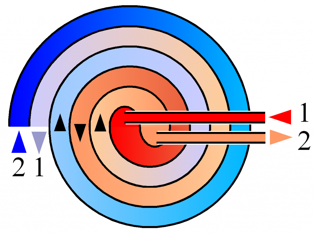 Schematic drawing of a spiral heat exchanger Deuts...
 English: An interchangeable plate heat exchanger a...
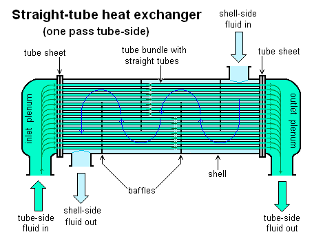 A Shell and Tube heat exchanger
The exiting MultiTherm leaves the first exchanger at approx. 250 oC. The MultiTherm enters the second heat exchanger at 250 oC and is cooled to 185 C by water at 20 oC, flowing at 2990 kg/hr. The water exits the exchanger at 50 oC. The cooled MultiTherm leaves the second exchanger and is accelerated by a pump before it enters the first exchanger to begin another cycle.
The MultiTherm coolant loop will consist of a schedule 80, 1.5 in. pipe that connects the two heat exchangers and the pump. The fluid will travel through 0.2 m of the 1.5 in. pipe between the two exchangers. 1.7 m of pipe will be between the cooling water exchanger and the pump. 1.3 m of pipe will be between the pump and ammonia heat exchanger.
The heat exchanger used for cooling the ammonia vapor will be 25.9 m in length with a 1.5 in. schedule 80 tube inside a 2.5 in. schedule 80 shell. The heat exchanger used for cooling the MultiTherm is 1.1 m in length with a 1.5 in schedule 80 tube inside a 2.0 in schedule 80 shell. A reservoir tank can be installed in the loop to replenish coolant that may be lost. Gate valves will be installed on either side of the two exchangers to assure ease of maintenance.
The recommended pump will require at least 0.06 hp, 10.8 m of head and 7.6 gpm flow rate. Our team chose a pump by MultiTherm with 0.312 hp, and model number: g1x.75x6.5 The 1/1000 scale down pump will require 1,018,000 hp, which is an unrealistic pump size.
Limitations to our design lie in the length of the heat exchanger used for cooling the ammonia vapor. A 26-meter heat exchanger is rather long and given a lack of space in the plant, this may not be possible. An alternative to this would be to add an additional heat exchanger for cooling the ammonia vapor, so two shorter exchangers will replace the longer one.
Besides the given length of the ammonia heat exchanger, we are confident that the above system gives the most efficient heat transfer with minimal cost and material.
This is a duplicate essay
this is a duplicate essay
2 out of 2 people found this comment useful.