1
Electromagnetic Tether Robot
EECE-281: Electrical and Computer Engineering laboratory
Professor: Dr. Jesus Calvino-Fraga, P.Eng.
L2C - CA
Sizhe Gao 12009122
Xiaoqing Li 18508127
Jingwen Lu 49019110
Le Ruan 35789122
Henry Xia 36270114
Lichen Yan 10645125
Date of Submission: Monday, April 7, 2014
2
Table of contents
1. Introductionâ¦â¦â¦â¦â¦â¦â¦â¦â¦â¦â¦â¦â¦â¦â¦â¦â¦â¦â¦â¦â¦â¦â¦â¦â¦â¦â¦ â¦â¦â¦...3
2. Investigation â¦â¦â¦â¦â¦â¦â¦â¦â¦â¦â¦â¦â¦â¦â¦â¦â¦â¦â¦â¦â¦â¦â¦â¦â¦â¦â¦â¦â¦â¦.6
a. Idea Generationâ¦â¦â¦â¦â¦â¦â¦â¦â¦â¦â¦â¦â¦â¦â¦â¦â¦â¦â¦â¦â¦â¦â¦â¦.â¦..6
b. Investigation Designâ¦â¦â¦â¦â¦â¦â¦â¦â¦â¦â¦â¦â¦â¦â¦â¦â¦â¦â¦â¦â¦â¦.â¦...6
c. Data Collectionâ¦â¦â¦â¦â¦â¦â¦â¦â¦â¦â¦â¦â¦â¦â¦â¦â¦â¦â¦â¦â¦â¦â¦â¦â¦â¦6
d. Data Synthesisâ¦â¦â¦â¦â¦â¦â¦â¦â¦â¦â¦â¦â¦â¦â¦â¦â¦â¦â¦â¦â¦â¦â¦â¦â¦â¦.7
e. Analysis of Resultsâ¦â¦â¦â¦â¦â¦â¦â¦â¦â¦â¦â¦â¦â¦â¦â¦â¦â¦â¦â¦â¦â¦â¦â¦..8
3. Design â¦â¦â¦â¦â¦â¦â¦â¦â¦â¦â¦â¦â¦â¦â¦â¦â¦â¦â¦â¦â¦â¦â¦â¦â¦â¦â¦â¦â¦â¦â¦â¦â¦..8
a. Use of Processâ¦â¦â¦â¦â¦â¦â¦â¦â¦â¦â¦â¦â¦â¦â¦â¦â¦â¦â¦â¦â¦â¦â¦.â¦â¦â¦.8
b. Need and Constraint Identificationâ¦â¦â¦â¦â¦â¦â¦â¦â¦â¦â¦â¦â¦â¦..â¦â¦.......9
c. Problem Specificationâ¦â¦â¦â¦â¦â¦â¦â¦â¦â¦â¦â¦â¦â¦â¦â¦â¦â¦â¦..â¦â¦â¦â¦9
d. Solution Generationâ¦â¦â¦â¦â¦â¦â¦â¦â¦â¦â¦â¦â¦â¦â¦â¦â¦â¦â¦â¦...â¦â¦â¦10
e. Solution Evaluationâ¦â¦â¦â¦â¦â¦â¦â¦â¦â¦â¦â¦â¦â¦â¦â¦â¦â¦â¦â¦â¦...â¦â¦.12
f. Detailed Designâ¦â¦â¦â¦â¦â¦â¦â¦â¦â¦â¦â¦â¦â¦â¦â¦â¦â¦â¦â¦â¦..â¦â¦â¦...13
g. Solution Assessmentâ¦â¦â¦â¦â¦â¦â¦â¦â¦â¦â¦â¦â¦â¦â¦â¦â¦â¦â¦â¦â¦â¦â¦..18
4. Live-long learningâ¦â¦â¦â¦â¦â¦â¦â¦â¦â¦â¦â¦â¦â¦â¦â¦â¦â¦â¦â¦â¦â¦â¦â¦â¦â¦...â¦19
5. Conclusionâ¦â¦â¦â¦â¦â¦â¦â¦â¦â¦â¦â¦â¦â¦â¦â¦â¦â¦â¦â¦â¦â¦â¦â¦â¦â¦â¦â¦â¦â¦â¦.20
6. Referenceâ¦â¦â¦â¦â¦â¦â¦â¦â¦â¦â¦â¦â¦â¦â¦â¦â¦â¦â¦â¦â¦â¦â¦â¦â¦â¦..â¦â¦â¦â¦â¦.20
7. Bibliographyâ¦â¦â¦â¦â¦â¦â¦â¦â¦â¦â¦â¦â¦â¦â¦â¦â¦â¦â¦â¦â¦â¦â¦â¦..â¦â¦...â¦â¦â¦21
8. Appendicesâ¦â¦â¦â¦â¦â¦â¦â¦â¦â¦â¦â¦â¦â¦â¦â¦â¦â¦â¦â¦â¦â¦â¦â¦â¦â¦â¦â¦â¦â¦â¦22
3
1. Introduction
1.a. Design Objective
For the second project of EECE 281, the team was asked to design, build, program, and test a
small autonomous robot in which the robot must be battery operated and controlled using a
microcontroller system. The robot must keep a fixed distance from an electromagnetic beacon. If
the beacon changes position, the robot must adjust its position to keep a constant distance from
the beacon. There should have at least four pieces of command from the transmitter: move closer,
move farther, turn 180 degree, and parallel parking, which the robot should follow.
1.b. Design Specifications
There were three major parts in designing this autonomous robot: the beacon, receiver and the
motor. In order to make these parts work as a whole, programs were written separately for the
beacon: - the data transmission program, and for the receiver located on the chassis. The
software programming on the microprocessors (AT89LP828 Microcontroller chip) was
implemented using C programming language.
The microprocessor on the beacon generated two square wave signals in different phases that
produced a strong magnetic wave using an LC circuit. There were also four buttons on the
microprocessor that sent signal to make the robot move forward and backward, turn 180 degree,
and parallel parking. There was another button on the transmitter to turn on/off the sensing mode
of the robot.
Another microcontroller system was used for the receiver that read the signal using two inductive
4
sensors and then determined the distance and direction from the beacon. The robot can sense the
signal from the transmitter at a minimum distance of 40cm. The furthest distance the car could
reach was 110 cm away from the beacon. The standard chassis was designed and distributed as a
part of a toolkit for the project.
1.c. Design Approach
1.c.1. Hardware Design Overview
5
1.c.2. Software Design Overview
6
2. Investigation
2.a. Idea Generation
Before the group started working on the project, there were two meetings discussing about the
general requirements of the project, as well as gathering ideas from each group member.
Different part was assigned to each member to carry on individual research. Then for the third
meeting, everyone came prepared with their researches and hypotheses. Each possible hypothesis
was discussed together as a team and chose the most efficient plan.
Based on the previous labs, basic functioning blocks such as peak detector, amplifier, H-bridge, motor
and ADC can be easily implemented into this project. Hence, the next step need to be considered is how
to connect those blocks together and how to implement LC circuit for signal transmission.
2.b. Investigation Design
By reading through the PDF files on Connect thoroughly, the group had the initial understanding
about the requirements and basic components for the project. In order to gain deeper
comprehension about the functionalities of every functioning block, each previous lab was
studied again within the group. Some research was done about how to create magnetic fields
using inductors, as well as how to enhance the fields using amplifiers. Therefore, the group came
up with a list of components that would be needed, together with a sketch of the general circuits
for both transmitter and receiver.
2.c. Data Collection
7
Essentially the resonance frequency of the transmitter was calculated using equation (f =
)
[1] and was compared with the resonance frequency of the simple LC circuit, as shown in
Figure.4, measured by the oscilloscope to see whether they match or not. The resulted resonance
frequency is approximately 14.8 kHz by both calculation and measurement. Hence, the
transmitter circuit was assembled and coded using its resonance frequency as 14.8 kHz. The
functionality of the transmitter was tested using a detector composed of an inductor, a capacitor,
and a LED in parallel, as shown in Figure.5. However, in order to light up the LED, it required a
very significant magnetic field. Eventually, a more precise range of magnetic field was measured
by replacing the LED light with an oscilloscope.
2.d. Data Synthesis
8
The measured data was analyzed by comparing with calculated results, as well as by comparing
with other groups' to reach appropriate conclusion. Also, it was confirmed with the teaching
assistance about the correctness of the data before moving on to the next stage.
On the other hand, in order to magnify the signal received by the receiver, it was necessary to
attach two amplifiers to the inductors before the signals go through peak detectors. LM 324 was
used as amplifiers. Since the gain = R2/R1 and a gain of 100 is required, R2 is chosen to be 1000
k⦠and R1 is chosen to be 10 kâ¦. The schematics of amplifier are shown in Section 3.f.2 Figure
11.
2.e. Analysis of Results
Since the circuits were simulated successfully before assembling on the breadboard, the degrees
of error that can occur was limited. However, when there were errors occurred, they were
resolved by analyzing the correctness of each signal generated in the circuits.
Also, after testing the received voltage from the receiver inductors, a gain of 100 was proved to
be suitable for magnifying the voltage before going through peak detectors. Further adjustment
was done through the process of design and testing.
3. Design
3.a. Use of Process
The knowledge for the basic components was from the previous EECE 281 labs. Those basic
functioning blocks were built and tested before. Hence, the design was started based on those
existing circuits and was expanded from there. Then the design and the circuit were built and
9
simulated using Multisim before assembling the actual circuits onto the breadboards. Some
adjustments were made to the design until they were successfully simulated by Multisim. The
actual circuits were analyzed by comparing the outputs generated by oscilloscope with the
simulated results from Multisim to make sure they were reasonable. Sometimes consulting with
other groups and teaching assistances can be extremely helpful as well.
3.b. Need and Constraint Identification
One possible group of customers of this project are young children between age five and ten who
like playing around with toy cars. However, in order to reach safety requirements of children's
toys, every circuit needs to be put into a sealed chassis to prevent children from coming in
contact with any wires or chips. More importantly, the inductors need to be properly covered by
materials that neither conduct heat nor block signals, to protect children from burning themselves.
Also, in order to make the car look desirable, the chassis can be upgraded to look like a race car
instead of the ordinary features.
The product can also be used by police forces or militaries to scout unknown areas or packages
by adding a live camera on top of the car which transmits the footage wirelessly onto a remote
screen. Also, the transmitter can be connected to the receiver with a robotic arm so that its length
can be adjusted remotely. This design can then protect police and soldiers from walking into any
unknown situations which can risk their lives.
3.c. Problem Specification
One big challenge faced by the group was serial data transmission. Although the partial code for
serial data transmission was given by the instructor, the group decided to use a self-produced but
10
similar way to transmit data. However, it was really struggling that ADC could not get serial data
although peak detectors were able to give the correct voltage.
Also, in the code for receiver, two peak values from two inductors were read and saved into two
float variables, voltage_l for the left inductor and voltage_r for the right inductor. The magnitude
changed from 0 to approximately 3.7V. The group decided to work with this voltage because
these values can give a straight-forward examination on whether those basic blocks work
properly or not.
Having obtained the values, the group then had to choose the comparing standard for the sensing
mode. It has to be carefully decided since it will affect the sensitiveness of the robot in sensing
mode. Many adjustments have been done and a final solution has been reached.
3.d. Solution Generation
The main requirement for this project is to use microcontroller system to send signals from
transmitter. Then the receiver has to receive the signal and send commands to motors so that the
robot can react accordingly. The designed transmitter generates a strong magnetic field and the
receiver can receive signals within a range of 40cm to 110cm. The robot can also follow the
signal from the transmitter and move to wherever the transmitter points to, and at the same time,
keep a fixed distance of 40cm away from it. This distance can be adjusted by either changing the
preset distance in the code or adjusting the resistance of the variable resistor. In addition, there
are five buttons to control the movement of the robot: moving forward, moving backward,
turning 180 degrees, parallel parking, and deactivating the sensing mode.
11
After consulting with other groups, it was realized that the processing time of ADC has also to be
taken into consider. Therefore, there would be a delay on received serial data. Hence, the serial
data transmitted should be longer and the ADC timing need to be calibrated. Through many
adjustments and tests, it was found that the reacting time of ADC is approximately 0.4s.
Therefore the bit time was set to 0.2s and extra two zeros were sent after the start bit before the
actual serial data.
Also, after many adjustments and tests, it was decided that a ratio (voltage_l/voltage_r) of 1.1
and 0.9 is suitable for controlling the car from turning and a difference of 0.3V from the preset
distance ( equivalent voltage is 2V) is suitable for controlling the distance between the car and
transmitter. Therefore, as shown in Figure 6, if the voltage ratio (voltage_l/voltage_r) is greater
than 1.1 and smaller than 9, the car will turn right and if the voltage ratio is greater than 0.1 and
smaller than 0.9, the car will turn left. At the same time, if the detected average voltage is smaller
than the preset distance (2V) -0.3V, the car will move backward, and forward for an average
voltage greater than (preset distance+0.3V). If none of the conditions above applies, the car will
stay at its position without any movement.
12
3.e. Solution Evaluation
In the group's design, each section of the electromagnetically tethered vehicle and its
corresponding beacon was designed to meet the criteria given in the project instruction. The
beacon and receiver pair, for example, which was possibly the most critical part of the vehicle,
reliable sent signals up to a distance of 110cm, and the receiver side could accurately determine
the relative location of the beacon and thus react respectively. However, when the beacon was
shifted very quickly, the receiver sometimes became confused. This was the result of a trade-off
between micro-scale accuracy and macro-scale accuracy (if the motor speed was increased, the
vehicle could follow the beacon faster, but may have become inaccurate in smaller scales). The
13
serial data transmitter works by sending logic 0 and logic 1 signals. The receiver will wait for a
delayed time and then read the received signals. This design was chosen over others because it
was faster than others and worked with all the criteria; it was the most efficient option. The
motor system worked with pwm signals from the microcontroller, to an optoisolator, into two H-
bridges of MOSFETs to control the movement of the two DC motors. The motor ran at 60%
power, in order to have stable movements, as well as turning accuracy.
3.f. Detailed Design
3.f.1. Transmitter Design
a) Voltage Regulator (LM7805C) [2]
This chip is used for converting 9V input to 5V output. The detailed connection is shown in
Figure 7. The input channel is connected to 9V battery and the output channel is connected to the
Vcc port of the microcontroller.
b) H-Bridge
The H-Bridge changes the DC voltage to a square wave. The detailed circuit is shown in Figure 8.
14
The circuit uses 2* P12PF06 and 2*P16NF06. The resistor in the bridge has chosen to be 10k
and the two ports stating "signal from controller" are connected to P2.5 and P2.6 in the
microcontroller.
c) LC Circuit
The LC circuit has already been shown above in section 2.c Figure 4. The power is now replaced
by the output from the H-Bridge and the frequency is adjusted to its resonance frequency 14.7
kHz in the code. The inductor then will generate a strong magnetic field which will then be
detected by the receiver circuit.
d) Push Button
Figure 14 shows how to connect a push button into a circuit. In this project, 5 push buttons are
used, four for the basic requirement from the instruction, and one for activating/deactivating the
sensing mode of the robot.
15
3.f.2 Receiver Design
a) LC Circuit
The LC circuit in receiver has already been shown in Section 2.c Figure 5. The test LED is
removed and now becomes the input to the amplifier.
b) Amplifier (LM324)
Figure 10 shows the pin allocation of LM324 and Figure 11 shows the circuit connection of
LM324 used as an amplifier. The resistors chosen are 1000k and 10k as discussed before to give
16
a gain of 100. In the group's circuit, the outputs from the LC circuit are connected into channel 1
and channel 4 of the op-amp, being amplified 100 times, and then go into channel 2 and channel
3 of the op-amp, which are now used as peak detectors.
b) Peak Detector
This circuit is implemented twice for the two inductor circuits. The resistor used here is 10k and
the capacitor used is 220uF. The op-amp used is LM324. The power input is replaced by the
output from the amplifier channel and the output is measured across the RC parallel part.
d) ADC (MCP3004) [3]
17
Figure 12 shows the pin connection of the ADC (MCP3004). The CH0 and CH1 are connected
to the output of peak detectors. Hence by selecting channels, each peak value can be read directly
from ADC and then being compared by microcontroller.
e) DC Motors
Figure 13 shows the connection for DC motors, which uses 2* P12PF06 as P-MOSFET,
2*P16NF06 as N-MOSFET, LTV-847 as optoisolator, 47k as RT, and 1k as R0. It receives the
pwm input from microcontroller, and hence controls the speed and direction of the motors. Two
sets of DC motor circuits are required since the robot has two wheels.
3.f.3. Software Design
a) Code for Transmitter
The frequency of the transmitted signal is adjusted by changing the execution time of "wait0s"
function in the code. The longer the execution time, the smaller the frequency. After that, by
alternating P2.5 and P2.6, it can send a logic 1 signal and by making both of them 0, it can send a
logic 0 signal. Different states have different serial data transmitted: 1111 for activating sensing
18
mode, 0000 for moving forward, 0001 for moving backward, 0010 for turning 180 degrees, 0011
for parallel parking, and 0100 for deactivating sensing mode.
b) Code for Receiver
The logic block diagram for receiver sensing mode has been shown in the Section 1.c.2. Figure 3.
The basic logic blocks for receiver are GetSerialData, GetVoltage, commands to control the
movement of motor, and functions for each state.
Without any serial data transmitted (i.e. 1111), the microcontroller will first get the voltage from
ADC using GetVoltage, compare the voltages and decide which way to move in the sensing
mode. Once there is serial data received by GetSerialData, it will jump to each state respectively
(i.e. 0000 for model_1, 0001 for model_2, 0010 for model_3, 0011 for model_4, 0100 for
complement the variable "comp" and then proceed to deactivate sensing mode ). In each state,
there have different commands to control the movement of motors, for which will send different
pwm values to control the speed and directions.
3.g. Solution Assessment
The vehicle and beacon worked together well, the transmitter sending instructions to the vehicle,
and the vehicle receiving instructions and maintaining preset distances from the transmitter. The
vehicle also correctly determined if the beacon was to the left or right and moved to face it. With
a maximum working distance of 110 cm from the beacon, the vehicle could switch among 5
preset distances and kept those distances by moving with the beacon.
This design's strengths included the ability to move among 5 preset distances, and its maximum
distance of 110 cm, which was 60 cm more than the required maximum distance. The detection
19
of the relative horizontal displacement was accurate, up to a speed of about 45 degrees/second of
the beacon. Rather than the addition of extra features, our vehicle incorporated well-working
base features and the minimization of errors and glitches.
This design's weaknesses included the inability to detect sudden and large changes in horizontal
positions of the beacon, and sometimes executed unexpected movements during such occasions.
4. Live-long Learning
When we first started designing the project, we had obtained some knowledge about the
individual components from previous lab modules. However, it was still challenging to assemble
the whole circuit together. The greatest challenge that we had encountered was to pass the
correct signal to the robot from the transmitter using inductors. At first the idea of transmitting a
signal seemed to be vague, but as we learned more and more material from our other course
EECE 253, we were able to understand how MOSFET and LC circuit operated. Beside technical
skills, we also learned some important transferable skills including communication and problem
solving skills.
Communicating between group members is extremely important. Since it is difficult to gather all
of the members together, we created a facebook group to keep everybody in touch. Any changes
of the code or any new idea toward the project would be uploaded so every member will be on
the same page. When a dispute between ideas arises, effectively solve a problem and making
sure that there is consensus between the parties that are in conflict.
Beside communication skills, we also learned some important problem solving skills.
Throughout the design process of this project, from the initial brainstorming to prototyping,
20
many problems occurred. One of the biggest problems that we ran into was the microcontroller
ceasing to function. Through some testing, and also hints from the professors, we were able to
isolate the causes of the problem (such as the frying of the IC due to static electricity, or the
wrong connection of pins of the MOSFET bridge).
5. Conclusion
The robot car designed and created by our group chases the beacon from the standard distance of
50cm. The signal created by the С code logic and programmed into the microprocessor is
generated on the beacon, in our case it is a sinusoidal wave produced by turning the mosfets of
the "H" bridge on and off consecutively.
There is a lot of room for improvement. The whole circuit seems to be inefficient in terms of
current driven. As a result, a whole bunch of batteries had to be recharged and went to buy fresh
new battery just before the demo period. This is the part to be analyzeD and work on in order to
achieve better results for efficiency.
6. Reference
[1] Dr. Jesús Calviño-Fraga P.Eng, "EECE281/EECE282 Project 2: Electromagnetic
Tether Robot", January 27, 2014. Retrieved from:
https://connect.ubc.ca/bbcswebdav/pid-1931076-dt-content-rid-
7469216_1/courses/CL.UBC.EECE.281.201.2013W2.23944/EECE281_Project2_2014.pdf
21
[2]Texas Instruments, "LM78XX Series Voltage Regulators", May 2000 (Revised April 2013)
Retrieved from: http://www.ti.com.cn/cn/lit/ds/symlink/lm7805c.pdf
[3] Microchip, "2.7V 4-Channel/8-Channel 10-Bit A/D Converters with SPI⢠Serial Interface",
2007
Retrieved from: http://ww1.microchip.com/downloads/en/DeviceDoc/21295C.pdf
[4] Ruan Lourens, "Low Frequency Transmitter" , 2008
Retrieved from: http://ww1.microchip.com/downloads/en/AppNotes/00232B.pdf>
7. Bibliography
"8051 Programming in C." Hanel, Web.
<http://xa.yimg.com/kq/groups/21447185/1325886378/name/08>.
"AT89LP828 Datasheet." Atmel, Web. <http://www.atmel.com/Images/doc3654A.pdf>.
Huang, H.W.(2000). Using the MCS51 Microcontroller. New York: Oxford University Press.
"LM2904,LM358/LM358A,LM258/ LM258A." Datasheet Catalog. Fairchild Semiconductor,
Web.. <http://www.datasheetcatalog.org/datasheet/fairchild/LM358.pdf>.
22
"LTV-817 Datasheet." Octopart,
<http://datasheet.octopart.com/LTV-817-Lite-On-datasheet-124899.pdf>.
8. Appendices
8.1. Transmitter Code
#include <stdio.h>
#include <at89lp51rd2.h>
// ~C51~
#define CLK 22118400L
#define BAUD 115200L
#define BRG_VAL (0x100-(CLK/(32L*BAUD)))
//We want timer 0 to interrupt every 100 microseconds ((1/10000Hz)=100 us)
#define FREQ 10000L
#define TIMER0_RELOAD_VALUE (65536L-(CLK/(12L*FREQ)))
//These variables are used in the ISR
volatile unsigned char pwmcount;
volatile unsigned char pwm1;
long int a=0;
unsigned char _c51_external_startup(void)
{
// Configure ports as a bidirectional with internal pull-ups.
P0M0=0; P0M1=0;
P1M0=0; P1M1=0;
P2M0=0; P2M1=0;
P3M0=0; P3M1=0;
P2M0 &= 0B_1111_1110;
P2M1 |= 0B_0000_0001;
AUXR=0B_0001_0001; // 1152 bytes of internal XDATA, P4.4 is a general purpose I/O
P4M0=0; P4M1=0;
// Initialize the serial port and baud rate generator
PCON|=0x80;
SCON = 0x52;
BDRCON=0;
BRL=BRG_VAL;
BDRCON=BRR|TBCK|RBCK|SPD;
// Initialize timer 0 for ISR 'pwmcounter()' below
TR0=0; // Stop timer 0
TMOD=0x01; // 16-bit timer
// Use the autoreload feature available in the AT89LP51RB2
// WARNING: There was an error in at89lp51rd2.h that prevents the
// autoreload feature to work. Please download a newer at89lp51rd2.h
// file and copy it to the crosside\call51\include folder.
TH0=RH0=TIMER0_RELOAD_VALUE/0x100;
TL0=RL0=TIMER0_RELOAD_VALUE%0x100;
TR0=1; // Start timer 0 (bit 4 in TCON)
ET0=1; // Enable timer 0 interrupt
EA=1; // Enable global interrupts
23
return 0;
}
void wait100ms ()//wait 100ms
{
_asm
;For a 22.1184MHz crystal one machine cycle
;takes 12/22.1184MHz=0.5425347us
mov R2, #4
L3: mov R1, #210
L2: mov R0, #184
L1: djnz R0, L1 ; 2 machine cycles-> 2*0.5425347us*184=200us
djnz R1, L2 ; 200us*250=0.05s
djnz R2, L3 ; 0.05s*20=1s
ret
_endasm;
return;
}
void wait0s(void)
{
_asm
;For a 22.1184MHz crystal one machine cycle
;takes 12/22.1184MHz=0.5425347us
mov R2, #1
L6: mov R1, #1
L5: mov R0, #16
L4: djnz R0, L4 ; 2 machine cycles-> 2*0.5425347us*184=200us
djnz R1, L5 ; 200us*250=0.05s
djnz R2, L6 ; 0.05s*5=0.25s
ret
_endasm;
return;
}
void waitxs(void)
{
_asm
;For a 22.1184MHz crystal one machine cycle
;takes 12/22.1184MHz=0.5425347us
mov R2, #1
L9: mov R1, #1
L8: mov R0, #12
L7: djnz R0, L7 ; 2 machine cycles-> 2*0.5425347us*184=200us
djnz R1, L8 ; 200us*250=0.05s
djnz R2, L9 ; 0.05s*5=0.25s
ret
_endasm;
return;
}
void sendsignal( )
{
if(P2_5==1)
{
P2_5=0;
P2_6=1;
}
else
{
P2_5=1;
P2_6=0;
}
wait0s();
return;
}
void sendsignal_long( )
{
for(a=5000;a>0;a--)
24
{
if(P2_5==1)
{
P2_5=0;
P2_6=1;
}
else
{
P2_5=1;
P2_6=0;
}
waitxs();
}
return;
}
void main (void)
{
_c51_external_startup();
P2_5=1;P2_6=0;
while(1)
{
// sendsignal( );
if(P2_1 == 0)
{
P2_5=0;//star bit 0// 0 000 000 00
P2_6=0;
wait100ms();
P2_5=0;
P2_6=0;//0
wait100ms();
P2_5=0;
P2_6=0;//0
wait100ms();
P2_5=0;
P2_6=0;//0
wait100ms();
P2_5=0;
P2_6=0;//0
wait100ms();
P2_5=0;
P2_6=0;//0
wait100ms();
P2_5=0;
P2_6=0;//0
wait100ms();
P2_5=0;
P2_6=0;//stop bit 0
wait100ms();
P2_5=0;
P2_6=0;//0
wait100ms();
}
else if(P2_2 == 0)
{
P2_5=0;
P2_6=0;//0 start bit// 0 000 001 00
wait100ms();
P2_5=0;
P2_6=0;//0
wait100ms();
P2_5=0;
P2_6=0;//0
wait100ms();
P2_5=0;
25
P2_6=0;//0
wait100ms();
P2_5=0;
P2_6=0;//0
wait100ms();
P2_5=0;
P2_6=0;//0
wait100ms();
sendsignal_long();//1
P2_5=0;
P2_6=0;//stop bit 0
wait100ms();
P2_5=0;
P2_6=0;//0
wait100ms();
// P2_2=1;
}
else if(P2_3 == 0)
{
P2_5=0;
P2_6=0;// 0 start bit// 0 000 010 00
wait100ms();
P2_5=0;
P2_6=0;//0
wait100ms();
P2_5=0;
P2_6=0;//0
wait100ms();
P2_5=0;
P2_6=0;//0
wait100ms();
P2_5=0;
P2_6=0;//0
wait100ms();
sendsignal_long();//1
P2_5=0;
P2_6=0;//0
wait100ms();
P2_5=0;
P2_6=0;//stop bit 0
wait100ms();
P2_5=0;
P2_6=0;//0
wait100ms();
}
else if(P2_4 == 0)
{
P2_5=0;
P2_6=0;// 0 start bit//0 000 011 00
wait100ms();
P2_5=0;
P2_6=0;//0
wait100ms();
P2_5=0;
P2_6=0;//0
wait100ms();
P2_5=0;
P2_6=0;//0
wait100ms();
P2_5=0;
P2_6=0;//0
wait100ms();
26
sendsignal_long();//1
sendsignal_long();//1
P2_5=0;
P2_6=0;//stop bit 0
wait100ms();
P2_5=0;
P2_6=0;//0
wait100ms();
}
else if (P2_7 == 0)
{
P2_5=0;
P2_6=0;// 0 start bit//0 000 100 00
wait100ms();
P2_5=0;
P2_6=0;//0
wait100ms();
P2_5=0;
P2_6=0;//0
wait100ms();
P2_5=0;
P2_6=0;//0
wait100ms();
sendsignal_long();//1
P2_5=0;
P2_6=0;//0
wait100ms();
P2_5=0;
P2_6=0;//0
wait100ms();
P2_5=0;
P2_6=0;//stop bit 0
wait100ms();
P2_5=0;
P2_6=0;//0
wait100ms();
}
else
{
sendsignal();
}
}//while
}
8.2. Receiver Code
// This program shows how to connect and access the MCP3004 ADC
// to the LP51B board.
//
// (c) Jesus Calvino-Fraga 2014
// Not to be copied, used, or revised without explicit written
// permission from the copyright owner.
//
#include <math.h>
#include <stdio.h>
#include <at89lp51rd2.h>
#include <stdlib.h>
#include <time.h>
27
// ~C51~
#define CLK 22118400L
#define BAUD 115200L
#define BRG_VAL (0x100-(CLK/(32L*BAUD)))
//We want timer 0 to interrupt every 100 microseconds ((1/10000Hz)=100 us)
#define FREQ 10000L
#define TIMER0_RELOAD_VALUE (65536L-(CLK/(12L*FREQ)))
volatile unsigned char pwmcount=0;
volatile unsigned char pwm1;
volatile unsigned char pwm2;
volatile unsigned char pwm3;
volatile unsigned char pwm4;
unsigned int mode=0;
unsigned int direction=0;
float distance=2;
unsigned char _c51_external_startup(void);
void wait100ms (void);
void wait50ms (void);
void wait45degree (void);
void SPIWrite(unsigned char);
unsigned int GetADC(unsigned char);
float GetVoltage (unsigned char);
//void pwmcounter (void) interrupt 1;
void leftwheelforward(void);
void leftwheelbackward(void);
void rightwheelforward(void);
void rightwheelbackward(void);
void leftwheelstop(void);
void rightwheelstop(void);
unsigned char model_0(float, float, int);
unsigned char model_1(void);
unsigned char model_2(void);
unsigned char model_3(void);
unsigned char model_4(void);
int GetSerialMode (float);
int complement(int);
unsigned char _c51_external_startup(void)
{
// Configure ports as a bidirectional with internal pull-ups.
P0M0=0; P0M1=0;
P1M0=0; P1M1=0;
P2M0=0; P2M1=0;
P3M0=0; P3M1=0;
P2M0 &= 0B_1100_0000;
P2M1 |= 0B_0011_1111;
P3M0 &= 0B_0011_1111;
P3M1 |= 0B_1100_0000;
AUXR=0B_0001_0001; // 1152 bytes of internal XDATA, P4.4 is a general purpose I/O
P4M0=0; P4M1=0;
// Instead of using a timer to generate the clock for the serial
// port, use the built-in baud rate generator.
PCON|=0x80;
SCON = 0x52;
BDRCON=0;
BRL=BRG_VAL;
BDRCON=BRR|TBCK|RBCK|SPD;
TR0=0; // Stop timer 0
TMOD=0x01; // 16-bit timer
// Use the autoreload feature available in the AT89LP51RB2
// WARNING: There was an error in at89lp51rd2.h that prevents the
// autoreload feature to work. Please download a newer at89lp51rd2.h
// file and copy it to the crosside\call51\include folder.
TH0=RH0=TIMER0_RELOAD_VALUE/0x100;
28
TL0=RL0=TIMER0_RELOAD_VALUE%0x100;
TR0=1; // Start timer 0 (bit 4 in TCON)
ET0=1; // Enable timer 0 interrupt
EA=1; // Enable global interrupts
pwmcount=0;
return 0;
}
// Interrupt 1 is for timer 0. This function is executed every time
// timer 0 overflows: 100 us.
void pwmcounter (void) interrupt 1
{
if(++pwmcount>99)
pwmcount=0;
P2_0=(pwm1>pwmcount)?1:0;// left wheel
P2_1=(pwm2>pwmcount)?1:0;// left wheel
P2_2=(pwm3>pwmcount)?1:0;// right wheel
P2_3=(pwm4>pwmcount)?1:0;// right wheel
}
void main (void)
{
float voltage_l=0;//left sesnsor voltage
float voltage_r=0;//right sensor voltage
float voltage_ratio=voltage_l/voltage_r;
float voltage_ave= (voltage_l+voltage_r)/2;
int val=1111;
int comp = 0;
P2_4 = 0;
P2_5 = 0;
P3_6 = 0;
P3_7 = 0; //initialize LED
// float distance=2;
_c51_external_startup();
while(1)
{
voltage_l = GetVoltage(0);
voltage_r = GetVoltage(1);
voltage_ratio = voltage_l/voltage_r;
voltage_ave = (voltage_l+voltage_r)/2;
leftwheelstop();
rightwheelstop();
P3_6 = comp;
if(voltage_l <(distance*0.4))//start bit received
{
val=GetSerialMode(distance);
}
if (val==110)
{
comp = complement(comp);
}
else if (comp==0)
{
if (val==1111)
{
leftwheelstop();
rightwheelstop();
29
model_0(voltage_ratio, voltage_ave, direction);//sensing mode
voltage_l = GetVoltage(0);
voltage_r = GetVoltage(1);
voltage_ratio = voltage_l/voltage_r;
voltage_ave = (voltage_l+voltage_r)/2;
}
if (val==0)
{
model_1();//move forward
distance = GetVoltage(0);
val=1111;
}
if (val==1)
{
model_2();//move backward
distance = GetVoltage(0);
val = 1111;
}
if (val==10)
{
model_3();//180
leftwheelstop();
rightwheelstop();
if (direction==0)
{
direction = 1;
}
else
{
direction = 0;
}
distance = GetVoltage(0);
val = 1111;
}
if (val==11)
{
model_4();//parallel parking
leftwheelstop();
rightwheelstop();
distance = GetVoltage(0);
val = 1111;
}
else
{
val=1111;
}
}
else if (comp==1)
{
if (val==1111) //stop
{
leftwheelstop();
rightwheelstop();
}
if (val==0) //forward
{
leftwheelforward();
rightwheelforward();
wait100ms();
wait100ms();
30
wait100ms();
wait100ms();
wait100ms();
wait100ms();
wait100ms();
wait100ms();
leftwheelstop();
rightwheelstop();
val=1111;
}
if (val==1) //backward
{
P2_4 = 1;
leftwheelbackward();
rightwheelbackward();
wait100ms();
wait100ms();
wait100ms();
wait100ms();
wait100ms();
wait100ms();
wait100ms();
wait100ms();
leftwheelstop();
rightwheelstop();
val=1111;
P2_4 = 0;
}
if (val==10) //left turn
{
leftwheelforward();
rightwheelbackward();
P2_5 = 1;
wait45degree();
wait45degree();
P2_5 = 0;
leftwheelstop();
rightwheelstop();
val=1111;
}
if (val==11) //right turn
{
leftwheelbackward();
rightwheelforward();
P3_7 = 1;
wait45degree();
P3_7 = 0;
leftwheelstop();
rightwheelstop();
}
else
{
val=1111;
}
}
}
}
int GetSerialMode (float distance_1)
{
float voltage_l_1 = 0;
int j;
int x=0;
wait100ms();
for(j=0;j<4;j++)
31
{
x=x*10;//shift x left
voltage_l_1 = GetVoltage(0);
if(voltage_l_1 > (0.5*distance_1) )
{
x++;
}
wait100ms();
}
if(x==0)
{
P0_0 = 0;
}
else if(x==10)
{
P0_2 = 0;
}
else if(x==11)
{
P0_3 = 0;
}
return x;
}
void wait100ms (void) // wait 200ms
{
_asm
;For a 22.1184MHz crystal one machine cycle
;takes 12/22.1184MHz=0.5425347us
mov R2, #4
L3: mov R1, #248
L2: mov R0, #184
L1: djnz R0, L1 ; 2 machine cycles-> 2*0.5425347us*184=200us
djnz R1, L2 ; 200us*250=0.05s
djnz R2, L3 ; 0.05s*20=1s
ret
_endasm;
return;
}
void wait50ms (void) // wait 50ms
{
_asm
;For a 22.1184MHz crystal one machine cycle
;takes 12/22.1184MHz=0.5425347us
mov R2, #2
L9: mov R1, #239
L8: mov R0, #184
L7: djnz R0, L7 ; 2 machine cycles-> 2*0.5425347us*184=200us
djnz R1, L8 ; 200us*250=0.05s
djnz R2, L9 ; 0.05s*20=1s
ret
_endasm;
return;
}
void wait45degree (void) // wait 45
{
_asm
;For a 22.1184MHz crystal one machine cycle
;takes 12/22.1184MHz=0.5425347us
mov R2, #26
L6: mov R1, #80
L5: mov R0, #184
L4: djnz R0, L4 ; 2 machine cycles-> 2*0.5425347us*184=200us
djnz R1, L5 ; 200us*250=0.05s
32
djnz R2, L6 ; 0.05s*20=1s
ret
_endasm;
return;
}
void SPIWrite(unsigned char value)
{
SPSTA&=(~SPIF); // Clear the SPIF flag in SPSTA
SPDAT=value;
while((SPSTA & SPIF)!=SPIF); //Wait for transmission to end
}
// Read 10 bits from the MCP3004 ADC converter
unsigned int GetADC(unsigned char channel)
{
unsigned int adc;
// initialize the SPI port to read the MCP3004 ADC attached to it.
SPCON&=(~SPEN); // Disable SPI
SPCON=MSTR|CPOL|CPHA|SPR1|SPR0|SSDIS;
SPCON|=SPEN; // Enable SPI
P1_4=0; // Activate the MCP3004 ADC.
SPIWrite(channel|0x18); // Send start bit, single/diff* bit, D2, D1, and D0 bits.
for(adc=0; adc<10; adc++); // Wait for S/H to setup
SPIWrite(0x55); // Read bits 9 down to 4
adc=((SPDAT&0x3f)*0x100);
SPIWrite(0x55);// Read bits 3 down to 0
P1_4=1; // Deactivate the MCP3004 ADC.
adc+=(SPDAT&0xf0); // SPDR contains the low part of the result.
adc>>=4;
return adc;
}
float GetVoltage (unsigned char channel)// geting the voltage of the leftside of the car
{
return ( (GetADC(channel)*5.8)/(1023.0)); // VCC=4.84V (measured)
}
unsigned char model_0(float voltage_ratio_0, float voltage_ave_0, int direction_0)//sensing mode
{
if(voltage_ratio_0>1.1 && voltage_ratio_0<9)//go right
{
P3_7 = 1;
P2_5 = 0;
if(direction_0==0)
{
leftwheelforward();
rightwheelbackward();
}
else
{
leftwheelbackward();
rightwheelforward();
}
}
else if( voltage_ratio_0<0.9 && voltage_ratio_0>0.1)//go left
{
33
P2_5 = 1;
P3_7 = 0;
if(direction_0==0)
{
rightwheelforward();
leftwheelbackward();
}
else
{
rightwheelbackward();
leftwheelforward();
}
}
else if( voltage_ratio_0>9 || voltage_ratio_0<0.1)
{
leftwheelstop();//stop
rightwheelstop();
P2_5 = 0;
P3_7 = 0;
}
else
{
leftwheelstop();//stop
rightwheelstop();
P2_4 = 0;
P2_5 = 0;
P3_7 = 0;
if (voltage_ave_0< (distance-0.3))//go
{
P2_4 = 0;
if(direction_0==0)
{
leftwheelforward();
rightwheelforward();
}
else
{
leftwheelbackward();
rightwheelbackward();
}
}
else if(voltage_ave_0> (distance+0.3))//back
{
P2_4 = 1;
if(direction_0==0)
{
rightwheelbackward();
leftwheelbackward();
}
else
{
rightwheelforward();
leftwheelforward();
}
}
else
{
P2_4 = 0;
leftwheelstop();//stop
rightwheelstop();
}
}//else
return 0;
}
unsigned char model_1(void)/// small car follow remote in short distance.
{
leftwheelforward();
34
rightwheelforward();
wait100ms();
wait100ms();
wait100ms();
wait100ms();
leftwheelstop();//stop
rightwheelstop();
return 0;
}
unsigned char model_2(void)/// small car follow remote in longer distance
{
leftwheelbackward();
rightwheelbackward();
P2_4 = 1;
wait100ms();
wait100ms();
wait100ms();
wait100ms();
leftwheelstop();//stop
rightwheelstop();
P2_4 = 0;
return 0;
}
unsigned char model_3(void) // in this model the car will rotate 180 degree and after 2 seconds
in will turn back again;
{
leftwheelforward();
rightwheelbackward();
P2_5 = 1;
wait45degree();
wait45degree();
wait45degree();
wait45degree();
leftwheelstop();//stop
rightwheelstop();
P2_5 = 0;
return 0;
}
unsigned char model_4(void)// parallel parking model
{
P2_4 = 1;
leftwheelforward();
rightwheelbackward();
wait45degree();
leftwheelbackward();
rightwheelbackward();
wait45degree();
wait45degree();
wait45degree();
wait45degree();
wait45degree();
leftwheelbackward();
rightwheelforward();
wait45degree();
leftwheelstop();//stop
rightwheelstop();
P2_4 = 0;
return 0;
35
}
void leftwheelforward(void) // leftwheel go forward
{
pwm1=60;
pwm2=0;
return;
}
void leftwheelbackward(void) // leftwheel go backward
{
pwm1=0;
pwm2=60;
return;
}
void rightwheelforward(void) // rightwheel go forward
{
pwm3=55;
pwm4=0;
return;
}
void rightwheelbackward(void) // rightwheel go backward
{
pwm3=0;
pwm4=55;
return;
}
void leftwheelstop(void)
{
pwm1=0;
pwm2=0;
return;
}
void rightwheelstop(void)
{
pwm3=0;
pwm4=0;
return;
}
int complement(int comp_1)
{
if (comp_1 == 1)
{
comp_1 = 0;
}
else if (comp_1 == 0)
{
comp_1 = 1;
}
return comp_1;
}
 English: autonomous cleaning robot by Fuji Heavy I...
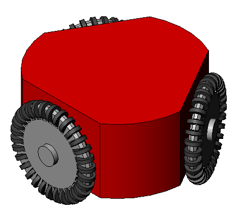 English: schematic drawing of an autonomous robot ...
 Image of Autonomous Robot From Second Grand Challe...