1. Introduction
This experiment involves the design of circuitry to implement a data transmission system. Information is entered via a keypad, and transmitted via an infra-red light emitting diode (LED) to a receiver, where signals are then decoded and displayed. The aims of this experiment were to demonstrate the use of an Erasable Programmable Logic Device (EPLD) to implement digital circuitry and the use of logic analysers to observe digital circuitry.
Some modules of this experiment required the use of state machines. We will cover this in more detail as state machines are an integral part of electronics due to it's pervasiveness in today's technology. Nowadays, regardless of how simple an electronic device may seem, be it a washing machine, vending machine or digital clock, it is most likely to contain state machines.
In this report, we will cover in detail the implementation of state machines in the transmitter and logic analyser and examine the errors involved in data transmission and reception and discuss how we can minimise its occurrence.
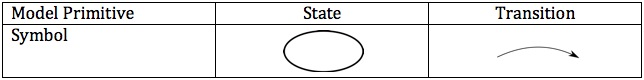 English: Short overview of the symbols used in Fin...
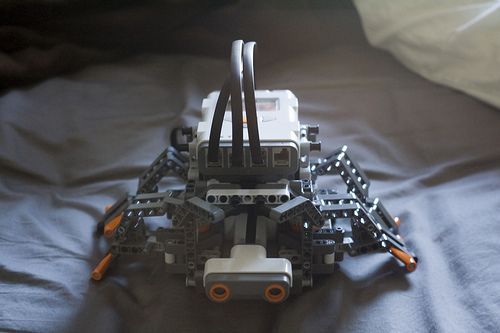 It's supposed to be a turtle
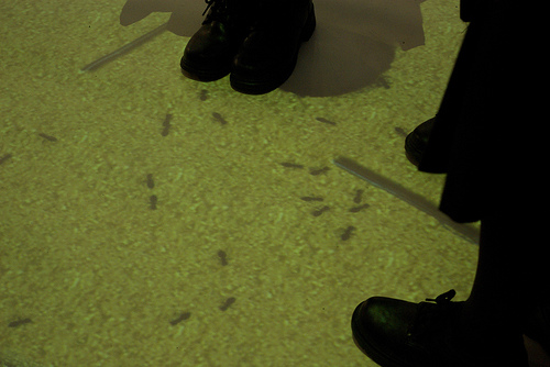 Antfarm interactive display at careers expo exhibi...
2. Theory
2.1 Software
All the software for the receiver and transmitter was written in MAX+PLUS II, a software package for designing and simulating digital systems. The system is based on hierarchy, decomposing the design into smaller modules. We will be focusing on higher level modules and avoiding the most bottom level design, which uses basic components such as gates and flip-flops to implement logic.
2.2 Data Transmission
The keypad consists of twelve standard buttons: digits 0 to 9, '#' and ' ' as shown below:
Figure 1: The keypad design
Whenever a key is pressed, the four bit binary representation of the key pressed is transmitted in the following pattern, a single start bit '1', four data bits, and three check bits of the sequence '010', giving a total of...