Outside Plant Outside plant is the network of cables, poles, conduit, feeder cable, distribution cable, terminals, aerial and drop wire, and fiber optics that interconnects CO's and connects from the local CO to the home or customer. The local loop or last mile is the link between the CO and the customer. The local loop is mainly made up of twisted-pair copper wire. Twisted-pair cables are classified by the wire gauge and the number of pairs within the sheath. The sizes vary from 1 pair to 3,600 pair. Wire gauges 19, 22, 24, 26 are used in the loop plant. The cost of the wire determines the use of the smallest wire possible with the best results. In other words smaller wire is used close to the CO and courser grade wire is used farther away from the CO to reduce loop resistance. Over the year the local loop has not changed much but there have been improvements in insulation, cable sheaths, splicing.
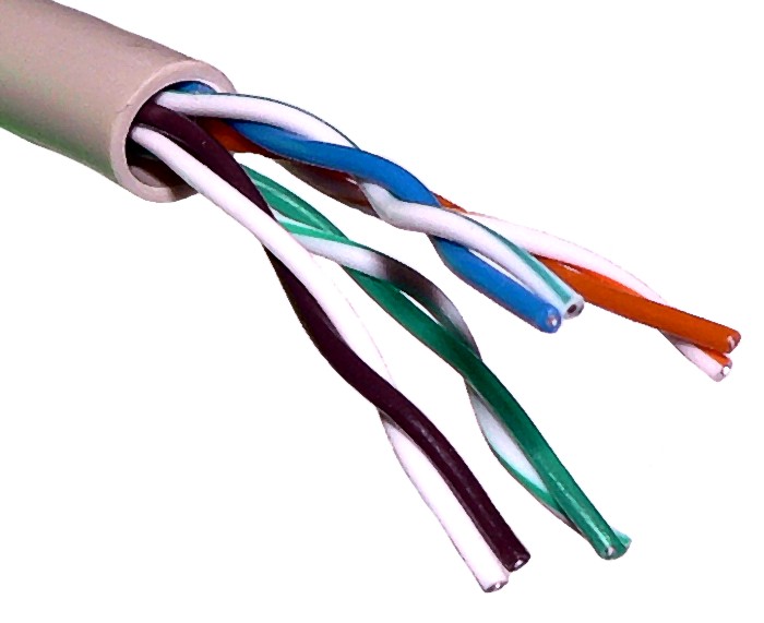 twisted pair utp cable
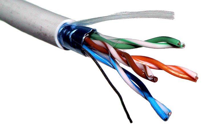 English: A stripped foiled twisted-pair (FTP) cabl...
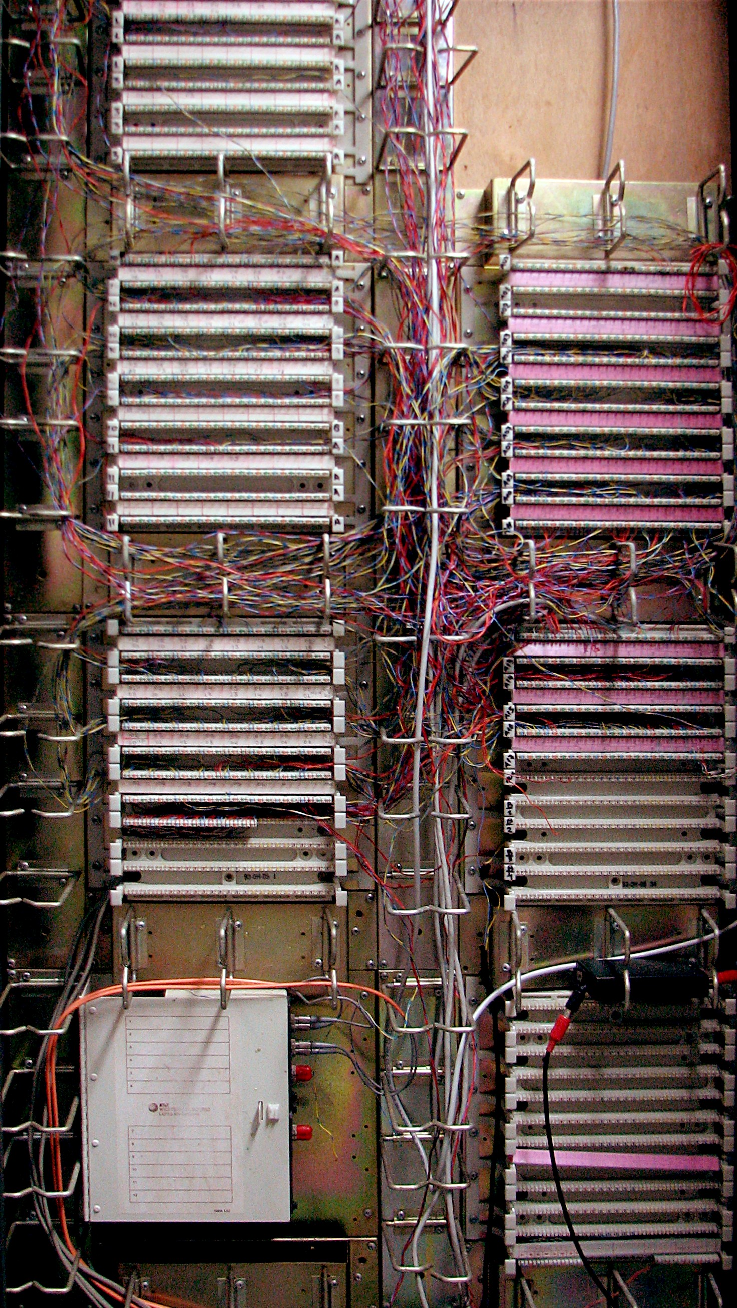 Unshielded twisted pair (copper) and optical fiber...
Most of the outside plant that was aerial has been converted to underground which reduces damage. The connection of CO's have changed dramatically by drunk routes being constructed in underground conduits about ever 6,000 feet. Copper wires can be changed to fiber optics, the material is unlimited, bandwidth provides greater performance, and does not corrode like copper. LEC's don't consider protection equipment and range extension as part of an outside plant.
Local loops are routed from the customer to the CO over twisted-pair cable. The twisted pair could be either aerial cable which is supported by poles. Aerial cable is being discontinued because of its vulnerability to damage. Aerial cable needs external strength for tension relief on the conductors. Direct burial is placed in the ground without a conduit. This method is ideal for rural areas because it is less expensive than conduit. LEC's can place several cables right after each other or where future additions may be needed, or they can place empty conduit to avoid a costly expansion in the future. The manholes are located at the maximum length cable can be physically handled at 6,000 foot intervals to house T-carriers and load coils.
The cable sheath that covers the cable is a highly durable plastic which may be polyethylene and polyvinyl chloride. Cable sheaths guard the cables from lightning, moisture, corrosion, rodents, and birds. In under water cases the wires are the sheath material, jute, and steel armor. Other than the sheath materials, metallic tape is grounded to each end to shield the cable from induction. The twisting of the cables is to preserve the electrical balance of the pair. If there is an unbalanced pair, noise may be a problem so the twist is to ensure the amount of coupling is minimized. Cable pairs are color coded within 50-pair complements. At splicing points the correct pairs and binding groups are splice together to ensure end-to-end pair identity and continuity. Cables can be spliced with compression sleeves or factory cut to the required length with connectors. Splicing quality is very important in preserving cable pair balance. The older splices where the wires were twisted together is often a source of imbalance because of insulation breakdown and splice deterioration. Splitting cable pairs can cause crosstalk. A split occurs when a wire from one pair is splice to a wire in another pair. cable splices are stored in above-ground closures in splice cases. The cables must be spliced and manufactured in order to prevent water from entering the sheath because moisture that gets inside of the cable is the most common cause of noise and crosstalk.
Loop resistance is determined by the wire gauge which engineers select. All telecommunication phone systems are limited to the loop resistance range they can tolerate. The cable gauge is to provide the desired resistance at the maximum temperature under which the system will tolerate also known as resistance design. Range is limited by the range of the CO such as the range which ringing can be supplied and tripped on answer. CO's normally have a loop resistance range from 1,300 to 1,500 ohms or more and PBX's have less which is about 400 to 800 ohms. A second consideration for selecting cables is the capacitance of the pair which is defined in microfarads per mile also referred to as (mf). An average customer's loop will normally have a high capacitance of 0.083 mf per mile.
Feeder cable and distribution cable divide the cable plant in half. Feeder cable routes cable pairs directly to an area with no intervention. Main feeders are backbone cables that leave the CO and are routed through a conduit to branching points. Branch feeders is a smaller cable that route pairs from the main feeder to the serving area. The distribution cable goes from the serving area to the customer. The distribution cable is terminated in terminals that may be on ground pedestals, buildings, aerial cable messenger, or underground. In an aerial or buried drop wire would connect from the terminal to the customer's protector. Both cable distributions are designed to avoid bridged tap, which is any portion that is not in the path of the user and CO.
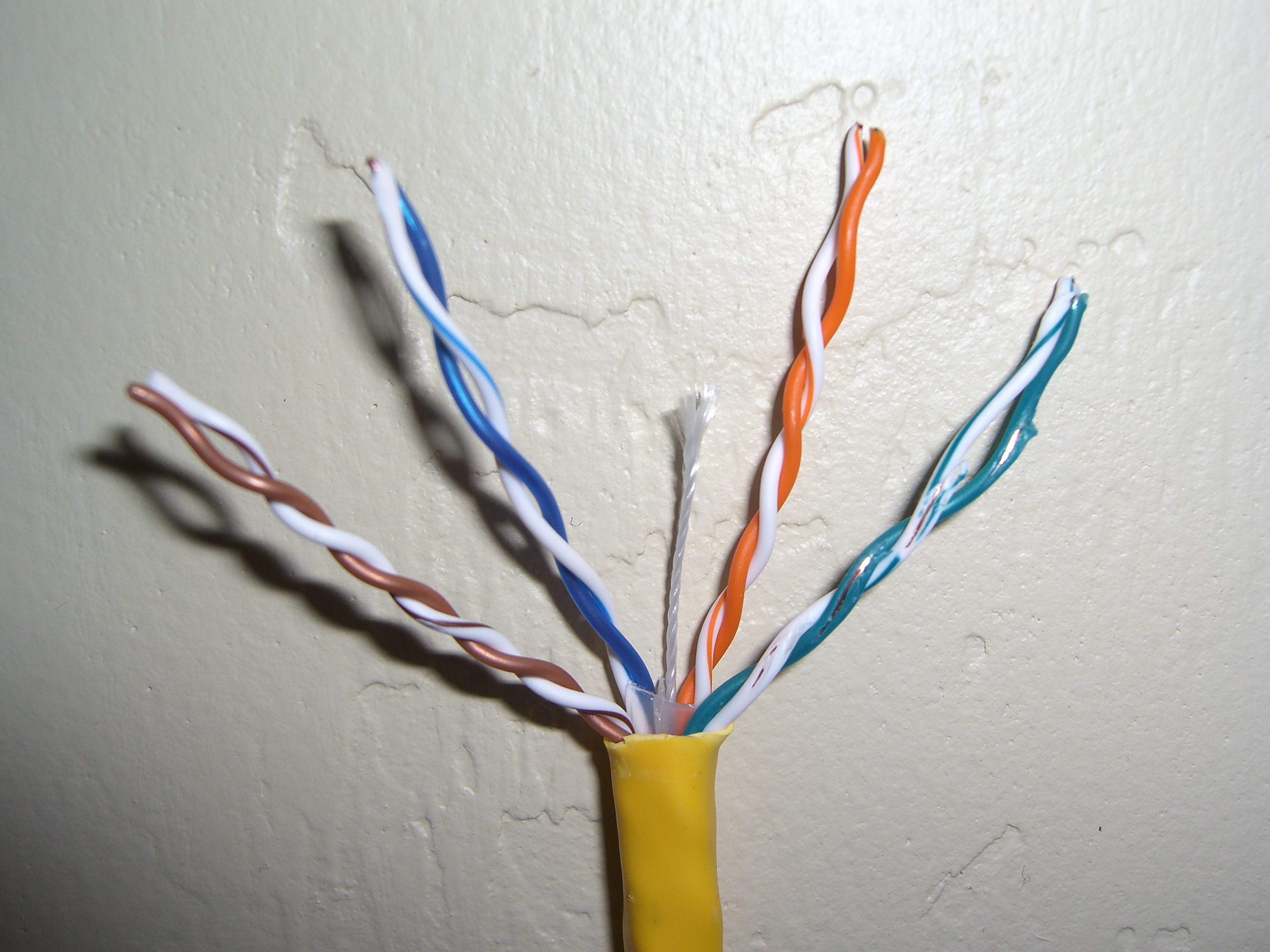 English: Category 6 twisted pair Ethernet cable
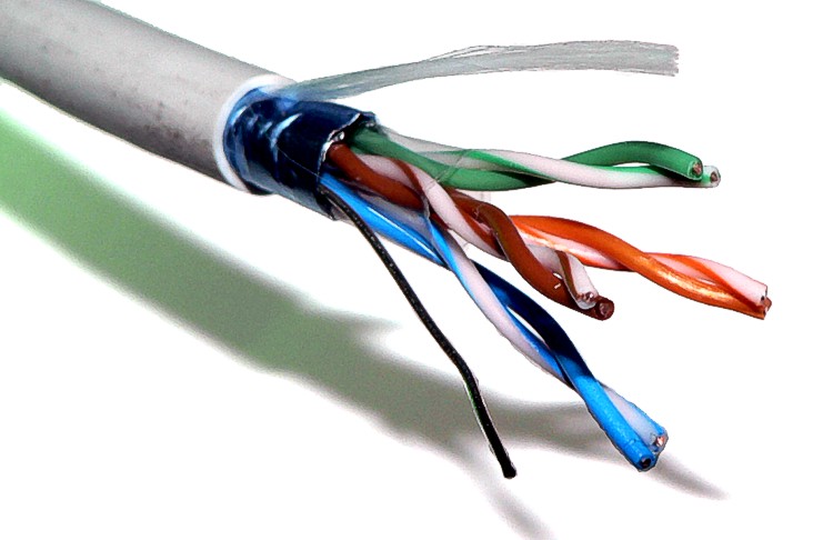 cable twisted pair FTP
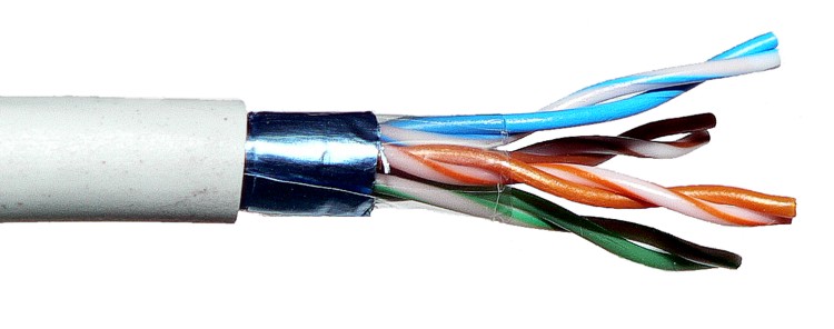 English: A stripped foiled twisted-pair (FTP) cabl...