HYDRAULIC BRAKES Brake Hydraulic System Principles & Service Tips.
Author/s: Bob Freudenberger Issue: Sept-Oct, 1999 Everyone who works on brakes MUST know these concepts and procedures In the early days of the automobile, some very clever engineering was employed to apply brakes mechanically. For example, the Italian Bugatti routed the cables over the top of the front axle so that the twisting action generated by stopping added force to the shoe cam lever.
No matter how ingenious the design, however, there was always a major drawback: Nothing could insure that braking force would be exactly equal at any pair of wheels, so there was a good chance that stepping on the pedal would cause swerving and skidding. This made the idea of hydraulically actuated brakes attractive--according to Pascal's Law, pressure at all points in a closed hydraulic system must necessarily be the same--but it took many years to develop dependable systems.
 List of car audio manufacturers and brands
 Photo © by Jeff Dean.
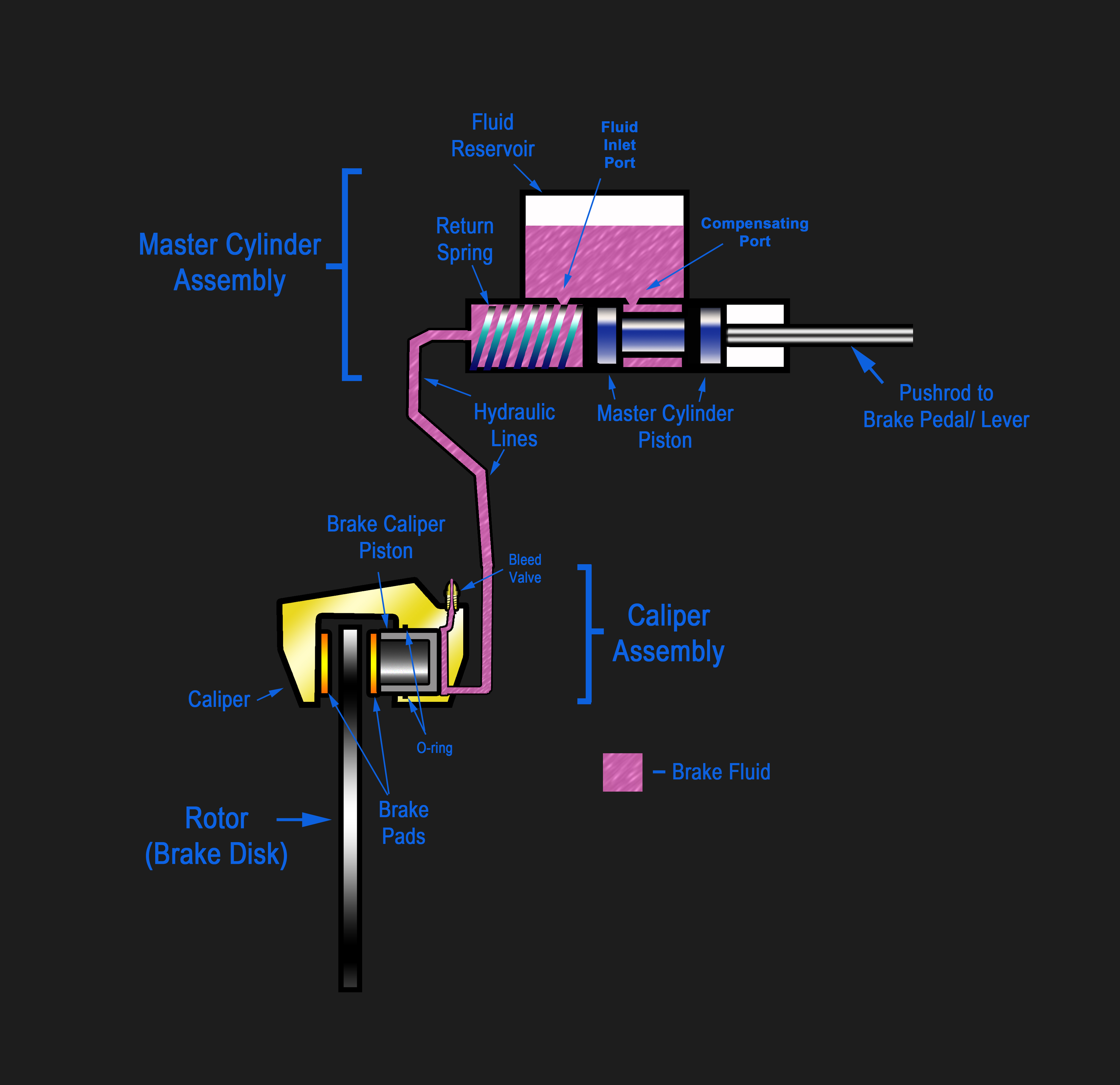 English: I generated this image personally, at muc...
The first car of any consequence to carry four-wheel hydraulic brakes was the. 1921 Dusenberg of the U.S.
Basic idea On the most basic level, all brake hydraulic systems share the same principle: Muscle strength amplified by leverage and perhaps a power booster displaces fluid from the master cylinder and causes pressure to increase all through the circuits. This overcomes the retracting springs in drums and the seals' elasticity in disc calipers and pushes the friction material against the rotating member.
That much is obvious, but the subtleties of modern designs that provide proper performance in the real world deserve some explanation. Hence this article, which also includes important service information every mechanic should know about.
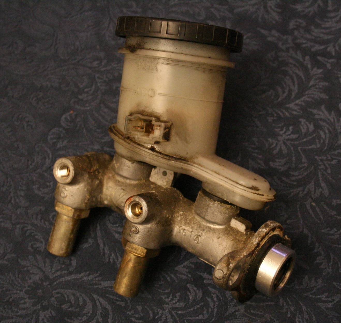
Dual master Although it has been in use for decades all over the world, the dual (also called "split" or "tandem") master cylinder is still widely misunderstood, so we had better explain its construction and operation. A typical late-model specimen will be of the composite variety (aluminum with a plastic reservoir), but iron one-piece units are still around in abundance. Two pistons ride in the bore, and here is where we encounter some confusing terminology. The rear piston is the primary, and the one in the front is the secondary. This apparent misnaming resulted because the rear piston is the first to receive the force of the driver's leg.
Each piston has a primary seal at its front and a secondary at its rear, so you will be hearing such combinations as primary piston secondary seal, secondary piston secondary seal, etc. The primary seals are the most important because they trap the fluid that is about to be squeezed into the lines. The primary piston's secondary seal keeps fluid from escaping out of the back of the cylinder (commonly into a booster), and the secondary piston's secondary seal acts as a barrier to make two essentially separate cylinders out of one.
In normal braking, the push rod from the pedal or booster forces the primary piston forward. No pressure is created until the primary seal covers the compensating or vent port from the reservoir. Once it does, fluid is trapped in the chamber between the pistons and becomes, for all intents and purposes, a solid column. Pressure is routed from this chamber to two wheels. The trapped fluid and the primary piston coil spring both bear on the secondary piston, moving it forward and creating pressure in the chamber ahead of the secondary piston's primary seal, to which the line to the other two wheels is attached.
Continued from page 1 When the pedal is released, a partial vacuum occurs in both pressure chambers because the fluid's inertia and viscosity prevent it from returning from the lines immediately. In order to re-arm the brakes instantaneously, the primary seals are designed to allow fluid to flow one way (forward) from behind each seal into the pressure chambers.
The replenishing ports allow fluid to move freely between the chambers behind both pistons' primary cups and the reservoir according to demand and expansion and contraction from temperature changes.
Second chance If a hose should rupture or one of the brake lines should become perforated from corrosion resulting in a catastrophic loss of fluid in half the system, the other half will still provide a means of decelerating the vehicle, albeit with a lower pedal and reduced stopping power.
Both pistons have extensions which project out in front of their primary seals. A failure in the circuit that is connected to the primary piston's pressure chamber will allow the piston to move forward enough so the extension will bear on the secondary piston, push it ahead, and generate pressure in the other circuit. If, on the other hand, the circuit that receives pressure from the secondary chamber springs a leak, the extension on the secondary piston will bottom out on the front of the cylinder and the fluid trapped between the pistons will operate the alternate set of brakes.
Extra displacement In the continuing effort by most automakers to wring every last bit of fuel efficiency out of cars, the resistance to rotation that zero-clearance discs cause is unacceptable. So, low-drag calipers were introduced. These have seal grooves machined at an angle, which cause the seals to retract the pistons enough to eliminate the parasitic loss. But this required a master cylinder that displaced a large volume of fluid during the initial part of the stroke in order to allow normal pedal travel and feel.
One common design uses a stepped bore and a primary piston with a small front and a larger rear diameter. At the beginning of the stroke, the large part of the piston naturally displaces more fluid than the small part, and this extra volume goes around the lip of the small seal into the chamber between the primary and secondary pistons, moving the secondary ahead more than the distance the push rod has traveled. This displaces extra fluid into both circuits. A special valve connected to the rear high-volume chamber vents excess fluid up into the reservoir once a certain amount of pressure is achieved. It also acts as the refill passage for the large chamber when the brakes are released.
Tailoring the pressure But there is more to an integrated brake hydraulic system than just a master cylinder. Means of fine-tuning the pressure for the situation and warning the driver of a partial failure are equally important to safe stopping. Various valves are used to perform the metering, proportioning, and warning light activation functions, and we will consider these jobs one at a time.
Continued from page 2 Disc brakes operate with very little clearance between the pads and the rotor, so the instant the caliper receives pressure, the drag on the wheel begins. Drums are different. There is considerable space to be taken up and the retracting springs must be overcome before the shoes can go to work. If a disc/drum combination were connected directly to the same master cylinder, the discs would end up doing far more than their share.
The metering or hold-off valve is what divides the work load properly. It stops the flow of fluid to the calipers until pressure reaches 5-9 BAR (70-130 psi), then it opens. This gives the drums a chance to catch up, so both types of brakes start applying at the same time. If you use a pressure bleeder during service, the metering valve will have to be deactivated, which is usually done by pulling or depressing a pin.
Proportioning Drum brakes are self-energizing and often duo-servo (that is, the shoes are not anchored at the bottom, which allows the leading shoe to rotate slightly when applied so that it pushes the trailing shoe tightly against the drum), whereas discs work entirely by means of hydraulic force. This situation can make drums lock up in hard stops. Weight transfer adds to the problem of rear over-braking, so even vehicles with discs at all four corners need some means of keeping the rear brakes within bounds.
The proportioning valve was invented to do this job. It limits the flow to the rear brakes after a certain pressure has been reached, and this "split point" can be anywhere from 14 to 35 BAR (200 to 500 psi). Above that, force in the rear lines is allowed to rise at only a portion of the maximum available. The valve does absolutely nothing in normal, low-pressure stops. On front/rear split systems, if the front circuit fails, the valve is bypassed to allow full hydraulic power to reach the rears.
A variation on this theme is the load-sensing proportioning valve, which you will find on some FWD cars and various small trucks. The distance between the body and the axle (which changes as the rear springs compress under load) is used to adjust rear stopping power to match the weight on the rear wheels and prevent lockup. Linkage connected to a lever on the proportioning valve varies the pressure available--the heavier the load, the more pressure is allowed to reach the rear brakes. In some systems having this feature, it is necessary that bleeding be done with the vehicle's weight on its wheels because the valve will shut off almost all flow with the axle hanging.
Help! The extra safety the dual brake system provides carries a subtle danger with it: If one half develops a leak and the driver is not sensitive enough to notice that he is pushing the pedal harder and farther than normal, he might continue to operate the vehicle indefinitely with severely inadequate brakes. So, a dash light is provided that comes on when one circuit has failed. This is activated by the pressure differential switch, which is essentially a piston that remains centered in its cylinder as long as there is equal pressure in both circuits. If one side suffers a significant fluid loss, the pressure of the other pushes the piston toward the open side, and this movement closes a switch that completes the electrical path to the warning light.
Continued from page 3 There is more than one way to divide a dual system. On RWD cars, the original approach was to put both fronts on one circuit and both rears on the other. That works fairly well should the rear brakes fail. But if the front circuit bursts, stopping power will be vastly reduced, and the vehicle will tend to skid if the rear wheels lock. With FWD, this situation became untenable because the rear wheels are so lightly loaded.
So, the dual-diagonal arrangement was introduced. Here, one front and one rear on opposite sides share a circuit. This required some additional components (two proportioning valves, for instance), but gave more reasonable emergency stopping ability in return. Bleeding sequence changed from the traditional Right Rear, LR, RF, LF to RR, LF, LR, RF.
While the growing popularity of ABS (Anti-lock Braking System) makes the subject very suitable for inclusion here, it is a topic that really deserves a whole article of its own. All we will say here is that the complex and expensive components involved make brake fluid changes--our next topic--much more important than it ever was before.
Replacing fluid, hoses, and lines Now for some service tips that should improve your reputation as a mechanic. Flushing and refilling the system with fresh fluid is certainly one. While you will not be able to eliminate every drop of the old, contaminated liquid without disassembling the calipers and cylinders, you can get enough out to effectively reduce the amount of moisture in the circuits. This has always been important for corrosion prevention, but now the high operating temperatures encountered with semi-metallic linings and FWD make maintaining a high boiling point critical to safety even for the average motorist (water-saturated fluid boils at a lower temperature than fresh fluid). There is also the benefit of removing sediment -- a combination of rust and the ashy residue of burned glycol.
Many carmakers now recommend fluid changes as preventative maintenance at intervals of from 20,000 to 50,000 km (12,000 to 30,000 miles).
Flexible brake hoses are so well made they often survive for the life of the car, but we consider their replacement valuable insurance against catastrophic failure. This attitude is supported by the service literature of several manufacturers. Some European factory service manuals state that hoses should be retired after 58,000 km (36,000 miles). This, however, will add quite a bit of extra expense to a brake job, so most mechanics use careful examination and their own judgement before choosing replacement. We have seen many cases of steel brake lines corroded to the point that they burst open, so we always make sure to examine them whenever we get under a car for any reason, and so should you. Especially where salt water is apt to be encountered, or where salt is used on roads in winter, rusted lines and the accidents they cause are common.
Bench bleeding Continued from page 4 Bench bleeding master cylinders is neglected so often it has become the number-one reason for both spongy pedal problems and returns to manufacturers of perfectly good units. Many brake parts suppliers even includes fittings, tubes, and/or plugs, and instructions in the box in hopes of eliminating this situation.
Although bench-bleeding can be done successfully by holding your fingers over the outlets to keep air from being drawn in on the return stroke, we recommend that you use either the tube or solid-plug method. Clamp one of the master's mounting ears in a vice (do not grip around the cylinder) so the unit is as level as possible. If you are using tubes, connect them to the outlet ports, position the tube tips well below the level of fluid in the reservoir, then use a rod or drift to stroke the piston SLOWLY. Wait at least 10 seconds between strokes to allow the chambers to release all their bubbles and fill completely. Keep stroking until there is no more evidence of air at the tube tips and ports.
Another good way to bench-bleed a master cylinder is to plug the outlets solid, then do normal 25mm (one-inch) strokes. Air will come up through the compensating ports until you get to what is called a "no-stroke" condition--you will only be able to move it a couple of millimeters (1/16 in. or so). That will tell you two things: One, you got all the air out. Two, the master cylinder is not bypassing.
If you get a car in with a replacement master cylinder that some other mechanic did not bench bleed, you might be able to perform this procedure with the master in place providing you can jack the rear of the vehicle high enough to get the cylinder level.
 English: Master cylinder from a 1990 Geo Storm GSi...
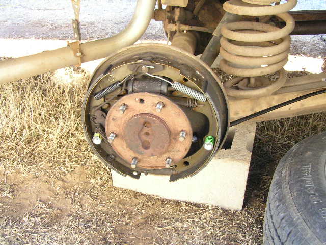 An 11" x 2" drum brake from a late 60's truck. Pho...
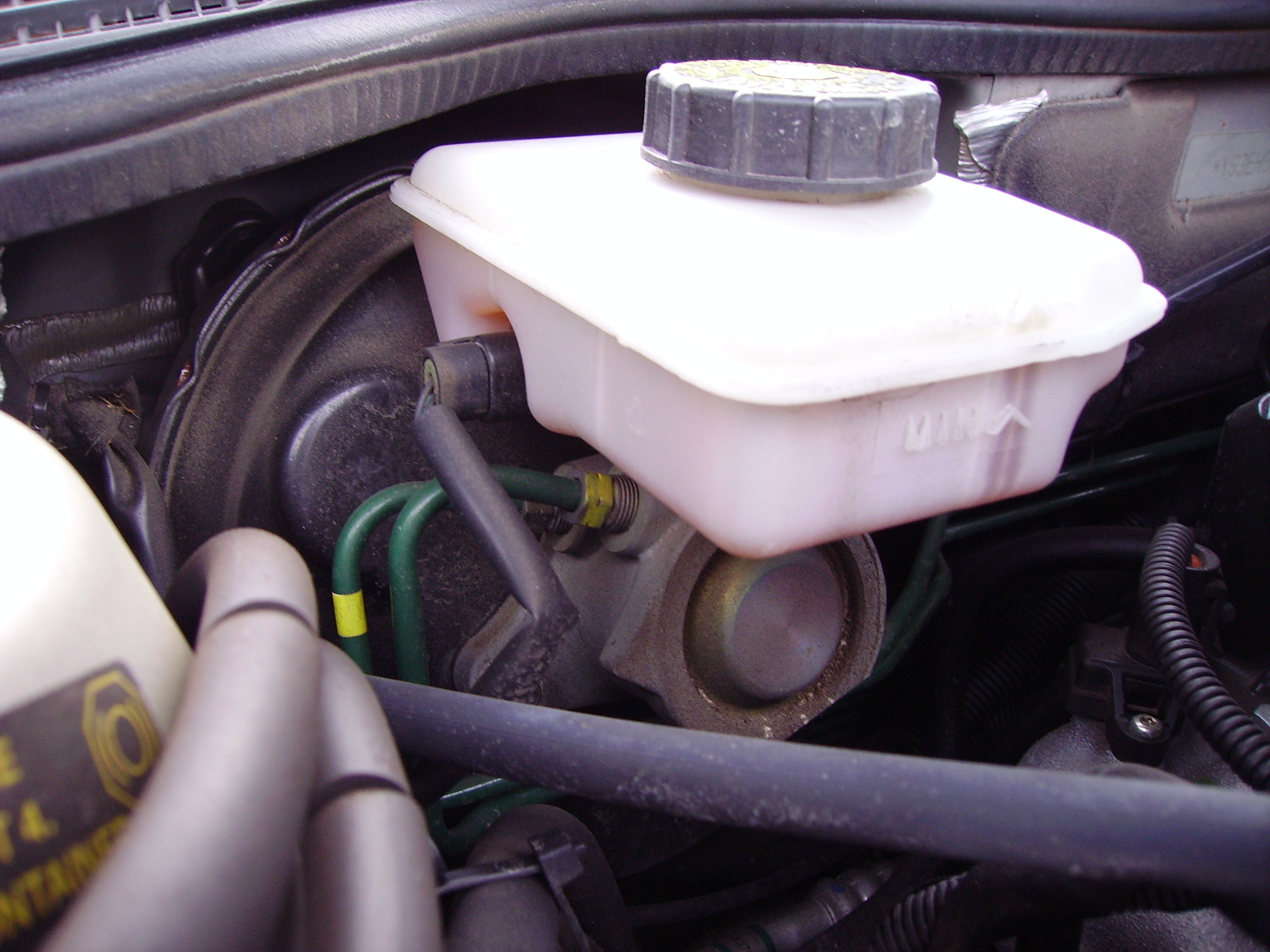 Brake master cylinder & reservoir (Saab 9-5)